Other Parts Discussed in Thread: MSP430FG4618, MSP-FET
Hello,
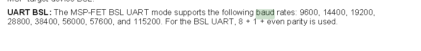
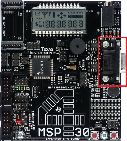
I got a new project with a MSP430FG4618/F2013 and i'm trying to communicate with my PC using a RS232 9-pin connection. I use IAR Embedded Workbench IDE and i use Tera Term to read the message on my computer. I read all the subjects on this forum and on the documentations and i found the three registers UCA0BR0, UCA0BR1 and UCA0MCTL. I understand what they does after reading all the docs. I tried to send at 9600, 14400, 38400 and 115 200 and it works. Now, i want to fix my baud rate to 288k (company rate) but i can't receive my message properly on my PC. For the registers, i use this site : 
I use a code i found in this thread : I just wanted something to send to my PC :
#include <msp430xG46x.h>
void TimerA_Init();
void USCIA0_UART_P2_Init();
void USCIA0_UART_Transmit(unsigned char c);
void SendString(char* str);
void SendBuffer(unsigned char* buf, unsigned short length);
void Handle_Incomming(unsigned char* pkt, unsigned short len);
#define RECEIVE_BUFFER_SIZE 128
#define PACKET_TERMINATION_CHAR '\n'
void main(void)
{
volatile unsigned int i,j; //Local Temp variable -- Volatile to prevent optimization
_DINT(); //Disable Interrupts -- For initialization purposes
WDTCTL = WDTPW + WDTHOLD; //Stop WatchDog
FLL_CTL0=(DCOPLUS|XCAP18PF); //Enable Frequency Multiplier (DCO+) and XIN/XOUT caps to 18pF
SCFI0=(FLLD_2 | FN_8); //Set Multiplier to 2 and DCO Range to 8Mhz Minimal
SCFQCTL=121; //7.995392Mhz Operation with No Modulation
//Configure USCI for UART Mode and Use P2.4 & P2.5 which are connected to the DB9 connector
UCA0CTL1 |= UCSWRST; //Configure the USCI with the reet bit held high
P4SEL &= ~0x0C0; //P4.7,6|=USCI_A0 RXD/TXD
P2SEL |= 0x30; //Set the USCI to use P2.4 and P2.5 for RX/TX
UCA0CTL1 |= UCSSEL_2; //USE SMCLK
UCA0BR0 = 0x1B; //Set bit Rate to 288kbps with a 8Mhz clock
UCA0BR1 = 0x00;
UCA0MCTL = 0xBB;
UCA0CTL1 &= ~UCSWRST; //Done Configuring so take USCI out of reset
IE2 |= UCA0RXIE;
TimerA_Init(); //Configure TimerA to generate an interrupt every second which will then transmit the message
P5DIR |= 0x02; //Set P5.1 to output direction -- LED is connected to this pin
_EINT(); //Done initializing so enable interrupt
while(1)
{
for (i=0;i<10000;i++)
{ for (j=0;j<50;j++)
;//LED BLINK DELAY
P5OUT ^=0x02; //Toggle P5.1 using XDR
}
}
}
void TimerA_Init()
{
TACTL = (TASSEL_1 | TACLR); //USE ACLK 32.768kHz and reset TAR
TACCTL0 = CCIE; //Enable the Capture/Compare Interrupt
TACCR0 = 32767; //The counter will reach 32767 in appox. 1second
TACTL |= MC_1; //Set it to run in 'up mode' and thus start the counter
}
#pragma vector = TIMERA0_VECTOR
__interrupt void Timer_A(void)
{
SendString("Hello World!\r\n"); //Transmit Hello World
}
#pragma vector=USCIAB0RX_VECTOR
__interrupt void USCIA0RX_ISR(void)
{
unsigned char ReceivedByte;
static unsigned char Buffer[RECEIVE_BUFFER_SIZE+1];
static int count=0;
ReceivedByte=UCA0RXBUF; //Retrieve the transmitted data from the receive buffer
if (ReceivedByte != PACKET_TERMINATION_CHAR || count >= RECEIVE_BUFFER_SIZE)
{
Buffer[count] = ReceivedByte;
count++;
}
else
{
Buffer[count] = ReceivedByte;
Buffer[++count] = PACKET_TERMINATION_CHAR; //Make sure it's terminated (needed in event of data overflow)
Handle_Incomming(Buffer, count); //Send completed packet to be processed
count = 0;
}
}
void Handle_Incomming(unsigned char* pkt, unsigned short len)
{
SendBuffer(pkt, len); //Don't process packet just rentransmit contents
return;
}
void USCIA0_UART_Transmit(unsigned char c)
{
while (!(IFG2&UCA0TXIFG)); //Wait until transmit buffer is empty
UCA0TXBUF=c; //Send character
return;
}
void SendString(char* str)
{
unsigned short i;
for (i=0;str[i]!='\0';i++)
USCIA0_UART_Transmit(str[i]); //Send String one character a a time
return;
}
void SendBuffer(unsigned char* buf, unsigned short length)
{
unsigned short i;
for(i=0; i<length; i++)
USCIA0_UART_Transmit(buf[i]); //Send Buffer one character at a time
return;
}
Thanks in advance.