This thread has been locked.

If you have a related question, please click the "Ask a related question" button in the top right corner. The newly created question will be automatically linked to this question.

Manchester Encoding/Decoding with MSP430

Other Parts Discussed in Thread: MSP430F5438A

I wanted to share my experience with implementing Manchester encoding/decoding on the MSP430 (specifically MSP430F5438A) because a brief search on the forums didn't fill me with confidence that it would be possible. I achieved rates of 1Mbit/s (target for my application) by using SPI & DMA modules for Encode and Timer & DMA modules for decode. This is necessary as an interrupt based solution only leaves a few clock cycles for processing (i.e. filling buffers - very tight, and leaves nothing for background tasks in the MCU) + lower power as CPU is off whilst encoding/decoding. I achieved 500uA on an evaluation board - so can probably be lower power with custom board and correct IO assignments, MCU sits in LPM0. (CPU MCLK = 25MHz).

Manchester Encoder:

  • In a RAM Buffer store either 0xF0 or 0x0F corresponding to 0 or 1 - the data changes twice as faster as the clock
  • Use the SPI module (MOSI output)
  • The SPI port needs to transmit the above bit/symbol at 1Mbit/s therefore SPI port is configured to run at 8MHz to achieve the 1Mbit/s line rate. 
  • Use a DMA channel to ensure no gaps appear between the bit symbols
  • Fill the buffer with the symbols you want and trigger by toggling the SPI_TXIFG flag.

Manchester Decoder:

  • Use Timer mode in capture mode to trigger on rising and falling edges.
  • Configure DMA to transfer timer values on triggers into RAM
  • Once packet received (use DMA counter register) study the timer values to determine if the symbol is a zero or a one (delta = T or T2)

I have found the MSP430 to be very flexible - just have to think through applications to find the right architecture.

  • Hi James,

    Thank you for sharing this interesting approach for a Manchester Encoder/Decoder. I have worked in a few implementations of it, and I can say that 1Mbps is pretty impressive. Variations of Manchester are used in many applications. Some require low-bitrates and can be implemented in simple MCUs without even using a timer, but many other protocols require increasingly higher frequencies and an efficient/smart use of peripherals, as you did. 

    Just as a few comments:

    The encoder implementation is using 1 byte of RAM for every bit of data; have you considered having multiple bits in a single byte (i.e. 0xA6 = 10100110 = '0010')? That could save you a some RAM and perhaps a little bit of power during transmission by running the SPI (and SMCLK?) at a lower frequency. 

    For the decoder, are you using some kind of ping-pong buffer to start decoding data after 'n' number of timer capture events? Or how do you know the DMA count? And do you have some kind of timer timeout to detect when the packet is complete?

    In any case, thank you for sharing this info. And feel free to share your code with the community, if you can and if you want :)

    Regards,

    Luis R

  • Hi Luis,

    Great to hear from you - its this sort of feedback I was aiming for.

    Luis RC said:

    In any case, thank you for sharing this info. And feel free to share your code with the community, if you can and if you want :)

    I am unable to share the code as I did it at work.

    Luis RC said:
    protocols require increasingly higher frequencies and an efficient/smart use of peripherals, as you did. 

    Indeed - the go-to device is a small FPGA for the application a few people in the team are working with. I wanted to prove to them that an MCU could do it. If the power budget sorts the FPGA then maybe its a no-brainer but even the msp430 at 25MHz is a lot less. Also maybe the development time would be quicker.

    Luis RC said:
    have you considered having multiple bits in a single byte (i.e. 0xA6 = 10100110 = '0010')

    Excellent point. The only impact this would have is reducing the 'error bars' on the receiver, as their would be fewer timer cycles between transitions. This would definitely be required if throughput of more than 1Mbit/s was needed as I think the SPI module is limited to 16MHz(?).

    Luis RC said:
    are you using some kind of ping-pong buffer to start decoding data after 'n' number of timer capture events?

    I am not at this stage because the latency was acceptable for my application. I have recently discovered that DMAxSZ does decrement showing progress of the RAM filling up - so it is definitely possible to try to process the incoming stream

    Luis RC said:
    And do you have some kind of timer timeout to detect when the packet is complete?

    . Also, my system is packet based and command/response.

    I am using the DMA interrupt to signal when the number of events has happened equals the packet. As both '1' and '0' have a transition in them that works.I have only tested with a small number of variatons in the payload - but I think this assumption is correct.

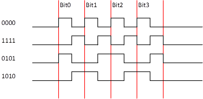
  • It might depend on your variation of Manchester (since there are different types of Manchester coding).

    A common one is when there is a transition in the middle of the bit (i.e. 0->1 ='1' and 1->0='0').

    So, assuming that your line low when idle and you are receiving only 4 bits of data:

    -0000 = 0 10101010 0 = 4 fall transitions, 4 falling

    -1111 = 0 01010101 0 = 4 rise transitions, 4 falling

    -0101 = 0 10011001 0 = 3 rise transitions, 3 falling

    -1010 = 0 01100110 0 = 2 rise transitions, 2 falling

    In the above case, I might never get the DMA complete event if I set my DMASIZE to 8 (rising & falling), but I might lose bits if I set it to 4. 

    One workaround is to have a timeout timer, which in this case could be set to >4 bit times. If you get the timeout, you can still check the DMA counter to see how many transfers are 'valid'.

    But if your manchester coding guarantees the same number of transitions for a packet, then this won't apply.

    Regards,

    Luis R


  • James Hillman said:


    have you considered having multiple bits in a single byte (i.e. 0xA6 = 10100110 = '0010')


    Excellent point. The only impact this would have is reducing the 'error bars' on the receiver, as their would be fewer timer cycles between transitions. This would definitely be required if throughput of more than 1Mbit/s was needed as I think the SPI module is limited to 16MHz(?).
    [/quote]

    Nothing says that you can't leave the receiver as is and use this method for the transmitter. For each nibble of raw data use it to index a 16-byte lookup table and place that in the transmit buffer. This way you get 4x the amount of time between transmit DMA interrupts (assuming your packet length is longer than the DMA can handle). The other benefit is that the transmit DMA hogs the internal data bus for 75% less time than current, leaving bus bandwidth for the CPU.

    On the receive side, I struggle to come up with a better solution, at least in the minute I take to type this.

**Attention** This is a public forum