- Ask a related questionWhat is a related question?A related question is a question created from another question. When the related question is created, it will be automatically linked to the original question.
I'm having some trouble figuring out if the following is even possible. The MSP430G2553 has the ADC10 peripheral with Data Transfer Controller (DTC). I'd like to use the DTC to copy the ADC10MEM directly to the USCI's Transmit Buffer (UCA0TXBUF) so it will be sent via UART. The idea is to sample as quickly as possible. I thought that one could possibly achieve a reasonable data rate by using the DTC to copy data directly to the UART, with carefully tuned baud rates and sample rates.
The UCA0TXBUF is an 8-bit register at address 0x0067, whereas ADC10MEM is a 16-bit register. Will the DTC even transfer data to an 8-bit register? I don't mind the register at 0x0068 to be overwritten as well. Unfortunately, I didn't find any discussion about valid DTC destinations in the Family User's Guide.
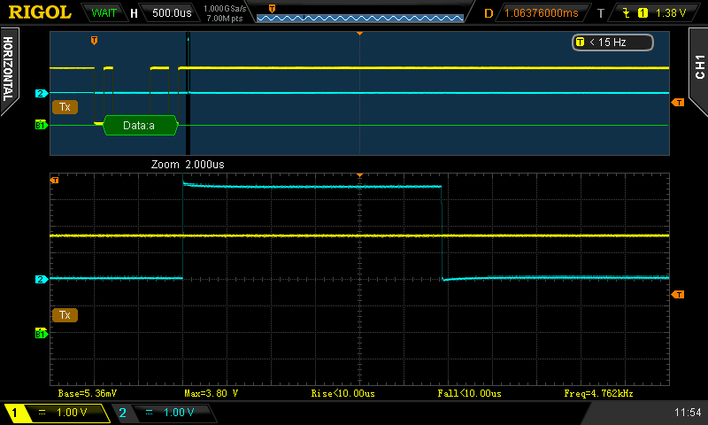
I attach my basic example code below. For ease of debugging, just one sample is captured and then the MCU enters an infinite loop. Unfortunately, I currently can't hook an oscilloscope to the UART pins. I'm using the MSP430G2553 on a Launchpad Rev 1.5.
- UART works, when the MCU starts, it will send an 'a'. I receive the 'a'.
- The ADC works, as ADC10MEM is copied to adcResult for debug purposes
- The DTC works when I point it to a variable in RAM (e.g. adcResult)
I expect to receive an 'a' and then some 8-bit value afterwards. However, I just receive the 'a' and then nothing happens.
I'm using the latest TI Compiler with CCSv6. The disassembly shows that the compiler generates the correct code:
106 ADC10SA = (unsigned short) &UCA0TXBUF;
c1b0: 40B2 0067 01BC MOV.W #0x0067,&ADC10_ADC10SA
So, my question is: Am I doing something wrong or will the ADC10's DTC not write to 8-bit registers?
#include <msp430.h>
#include <inttypes.h>

/*
 * main.c
 */
// MCU: msp430g2553

volatile uint16_t adcResult = 0;

int main(void) {
    WDTCTL = WDTPW | WDTHOLD;	// Stop watchdog timer

    init_clock();
    init_uart();
    UCA0TXBUF = 'a';		// test if uart works
    while(UCA0STAT & UCBUSY);
    init_adc();
    for(;;) {
    	while(ADC10CTL1 & ADC10BUSY);
    	adcResult = ADC10MEM;		// copy result into memory for debug purposes
    	for(;;);	// stop here
    }
	return 0;
}


void init_clock(void) {
	DCOCTL = 0;
	DCOCTL = CALDCO_16MHZ;
	BCSCTL1 = CALBC1_16MHZ;
}

void init_uart(void) {
	// select UART peripheral for pins P1.1 and P1.2
    P1SEL |= BIT1 | BIT2;
    P1SEL2 |= BIT1 | BIT2;

    // init uart clock
    UCA0CTL1 |= UCSSEL_2;
    // 9600/8/N/1
    // ucbrx = 1666, ucbrs = 6   -> uca0br0 = 130   uca0br1 = 6
	UCA0BR0 = 130;
	UCA0BR1 = 6;

	UCA0MCTL = UCBRS_6;

	UCA0CTL0 = 0;

	// enable UART
	UCA0CTL1 &= ~UCSWRST;
}

void init_adc(void) {
	ADC10CTL1 = INCH_5 | ADC10DIV_7 | ADC10SSEL_2;
	ADC10AE0 = BIT5;
	ADC10CTL0 = ADC10ON;

	// configure DTC
	ADC10DTC0 = ADC10CT;
	ADC10DTC1 = 1;
	ADC10SA = (unsigned short) &UCA0TXBUF;

	// start conversion
	ADC10CTL0 |= ENC | ADC10SC;
}
**Attention** This is a public forum