This thread has been locked.
If you have a related question, please click the "Ask a related question" button in the top right corner. The newly created question will be automatically linked to this question.
Hi Everyone,
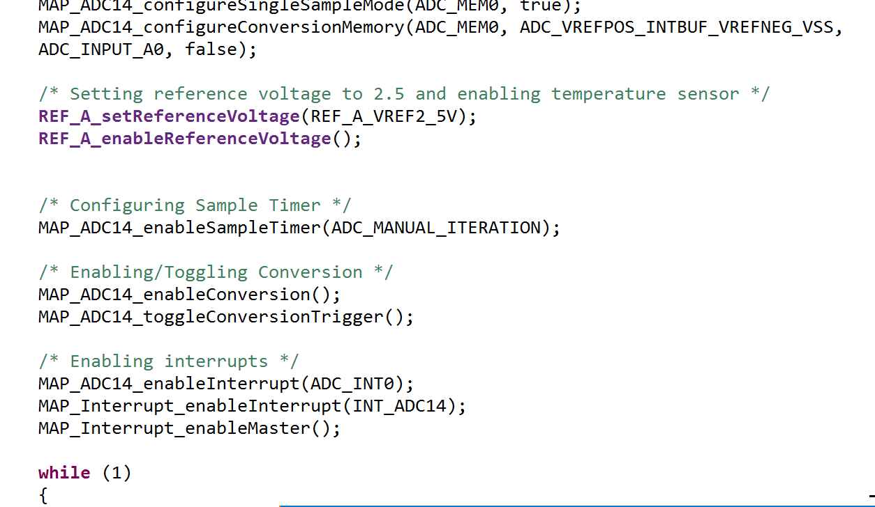
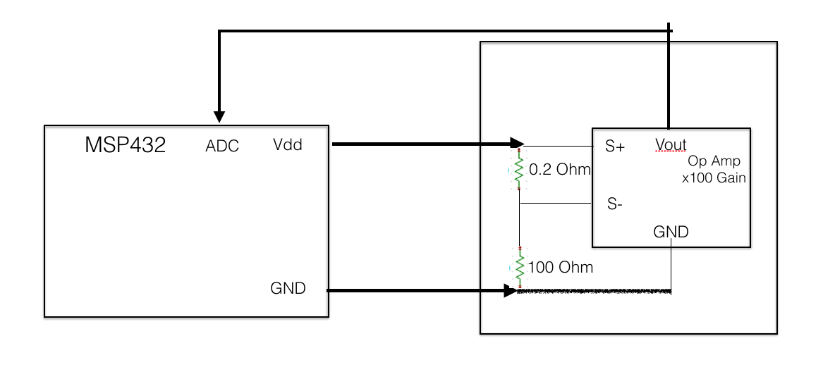
I am trying to use MSP432 on chip 14 bit ADC to sense output from a current sensing op-amp(https://datasheets.maximintegrated.c...s/MAX44284.pdf).
I am getting a large reading error from my ADC compare to the multimeter reading.
My question is
Do i need to have a front end amplifier to buffer the input to ADC, or I can directly sense it?
Thanks a lot,
Eddy
Hey Cameron,
I did try to repeat the measurement. I noticed more of percentage error. At low voltage ,The error is relatively smaller. However, at higher voltage ~1 or ~2V. The error is much higher which is around 10% to 20%.
This is directly measured from the output of max44284. (I did try to tie a op-amp in voltage follower configuration after the output. it helped a bit, but there are still errors)
But When i measured the voltage at the resistor.(Voltage divider). The error is less than 5mV across most of the voltage range.
I used the MSP432 internal reference 2.5V
Hi Cameron,
Thanks for the response.
1. Can you post the rest of your code? I'd like to see the rest of your settings (such as SHT, your ADC init, etc).
I did a quick modification to the example code" adc14_single_conversion.c". Here is the main code and project
2: Also, can you post a schematic? This will answer some other questions I have.
We did the test on the breadboard.
Here is the diagram, I used the multimeter(A34401) to measured the output. The ground probe of the multimeter is placed on the board
3. I'm not clear on where you are measuring with your dmm. You mention a voltage divider, is this before the MAX part? If so is it possible for you to measure the voltage after the MAX part?
Here is the diagram, I am saying, in this case , the ADC reading is very accurate. but the above case, The ADC gives me a large error compare to multimeter.
/* * ------------------------------------------- * MSP432 DriverLib - v3_21_00_05 * ------------------------------------------- * * --COPYRIGHT--,BSD,BSD * Copyright (c) 2016, Texas Instruments Incorporated * All rights reserved. * * Redistribution and use in source and binary forms, with or without * modification, are permitted provided that the following conditions * are met: * * * Redistributions of source code must retain the above copyright * notice, this list of conditions and the following disclaimer. * * * Redistributions in binary form must reproduce the above copyright * notice, this list of conditions and the following disclaimer in the * documentation and/or other materials provided with the distribution. * * * Neither the name of Texas Instruments Incorporated nor the names of * its contributors may be used to endorse or promote products derived * from this software without specific prior written permission. * * THIS SOFTWARE IS PROVIDED BY THE COPYRIGHT HOLDERS AND CONTRIBUTORS "AS IS" * AND ANY EXPRESS OR IMPLIED WARRANTIES, INCLUDING, BUT NOT LIMITED TO, * THE IMPLIED WARRANTIES OF MERCHANTABILITY AND FITNESS FOR A PARTICULAR * PURPOSE ARE DISCLAIMED. IN NO EVENT SHALL THE COPYRIGHT OWNER OR * CONTRIBUTORS BE LIABLE FOR ANY DIRECT, INDIRECT, INCIDENTAL, SPECIAL, * EXEMPLARY, OR CONSEQUENTIAL DAMAGES (INCLUDING, BUT NOT LIMITED TO, * PROCUREMENT OF SUBSTITUTE GOODS OR SERVICES; LOSS OF USE, DATA, OR PROFITS; * OR BUSINESS INTERRUPTION) HOWEVER CAUSED AND ON ANY THEORY OF LIABILITY, * WHETHER IN CONTRACT, STRICT LIABILITY, OR TORT (INCLUDING NEGLIGENCE OR * OTHERWISE) ARISING IN ANY WAY OUT OF THE USE OF THIS SOFTWARE, * EVEN IF ADVISED OF THE POSSIBILITY OF SUCH DAMAGE. * --/COPYRIGHT--*/ /******************************************************************************* * MSP432 ADC14 - Single Channel Sample Repeat * * Description: This code example will demonstrate the basic functionality of * of the DriverLib ADC APIs with sampling a single channel repeatedly. Each * time the ADC conversion occurs, the result is stored into a local variable. * The sample timer is used to continuously grab a new value from the ADC * module using a manual iteration that is performed in the ADC ISR. A * normalized ADC value with respect to the 3.3v Avcc is also calculated using * the FPU. * * MSP432P401 * ------------------ * /|\| | * | | | * --|RST P5.5 |<--- A0 (Analog Input) * | | * | | * | | * | | * | | * * Author: Timothy Logan ******************************************************************************/ /* DriverLib Includes */ #include "driverlib.h" /* Standard Includes */ #include <stdint.h> #include <stdbool.h> /* Statics */ static volatile uint16_t curADCResult; static volatile float normalizedADCRes; int main(void) { /* Halting the Watchdog */ MAP_WDT_A_holdTimer(); /* Initializing Variables */ curADCResult = 0; /* Setting Flash wait state */ MAP_FlashCtl_setWaitState(FLASH_BANK0, 2); MAP_FlashCtl_setWaitState(FLASH_BANK1, 2); /* Setting DCO to 48MHz */ MAP_PCM_setPowerState(PCM_AM_LDO_VCORE1); MAP_CS_setDCOCenteredFrequency(CS_DCO_FREQUENCY_48); /* Enabling the FPU for floating point operation */ MAP_FPU_enableModule(); MAP_FPU_enableLazyStacking(); /* Initializing ADC (MCLK/1/4) */ MAP_ADC14_enableModule(); MAP_ADC14_initModule(ADC_CLOCKSOURCE_MCLK, ADC_PREDIVIDER_1, ADC_DIVIDER_4, 0); /* Configuring GPIOs (5.5 A0) */ MAP_GPIO_setAsPeripheralModuleFunctionInputPin(GPIO_PORT_P5, GPIO_PIN5, GPIO_TERTIARY_MODULE_FUNCTION); /* Configuring ADC Memory */ MAP_ADC14_configureSingleSampleMode(ADC_MEM0, true); MAP_ADC14_configureConversionMemory(ADC_MEM0, ADC_VREFPOS_INTBUF_VREFNEG_VSS, ADC_INPUT_A0, false); /* Setting reference voltage to 2.5 and enabling temperature sensor */ REF_A_setReferenceVoltage(REF_A_VREF2_5V); REF_A_enableReferenceVoltage(); /* Configuring Sample Timer */ MAP_ADC14_enableSampleTimer(ADC_MANUAL_ITERATION); /* Enabling/Toggling Conversion */ MAP_ADC14_enableConversion(); MAP_ADC14_toggleConversionTrigger(); /* Enabling interrupts */ MAP_ADC14_enableInterrupt(ADC_INT0); MAP_Interrupt_enableInterrupt(INT_ADC14); MAP_Interrupt_enableMaster(); while (1) { MAP_PCM_gotoLPM0(); } } /* ADC Interrupt Handler. This handler is called whenever there is a conversion * that is finished for ADC_MEM0. */ void ADC14_IRQHandler(void) { uint64_t status = MAP_ADC14_getEnabledInterruptStatus(); MAP_ADC14_clearInterruptFlag(status); if (ADC_INT0 & status) { curADCResult = MAP_ADC14_getResult(ADC_MEM0); normalizedADCRes = (curADCResult * 2.5) / 16384; MAP_ADC14_toggleConversionTrigger(); } }
Hi Cameron,
Any suggestions? Did you see anything strange in my code ? I did a minimum modification the example code.
Thanks,
Eddy
Eddy,
I'm going to close this due to inactivity. We can always re-open it if needed, jut let me know if that's the case.
**Attention** This is a public forum