This thread has been locked.

If you have a related question, please click the "Ask a related question" button in the top right corner. The newly created question will be automatically linked to this question.

MSP430FR2652 (MSP430FR2632IRGET) programmer fail!

Other Parts Discussed in Thread: MSP430FR2311, MSP430FR2632, MSP-EXP430FR2311, MSP430G2553

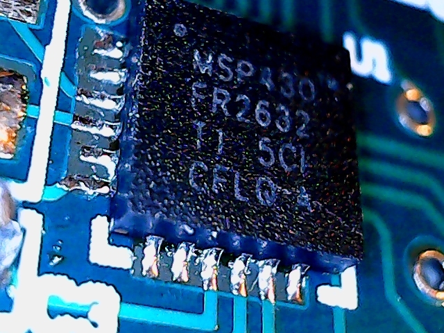
I`m working in a new design with MSP430FR2632IRGET ( I draw and assembly my prototype ) board, but I can`t program the microcontroller. I use as JTAG interface the board MSP430FR2311 LAUNCHPAD. WHEN i TRY TO TRANSFER THE FIRMWARE TO MY BOARD BUT THE CODE COMPOSER RETURNED FAIL CONNECTION. 

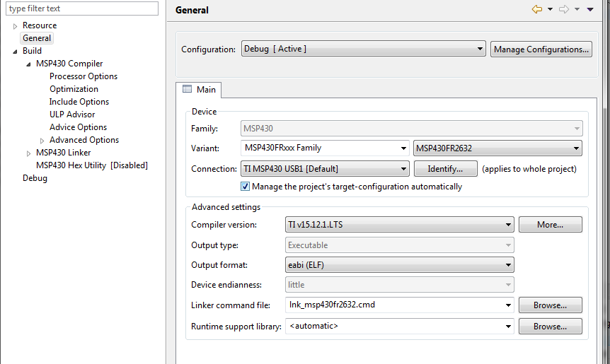
The target configuration 

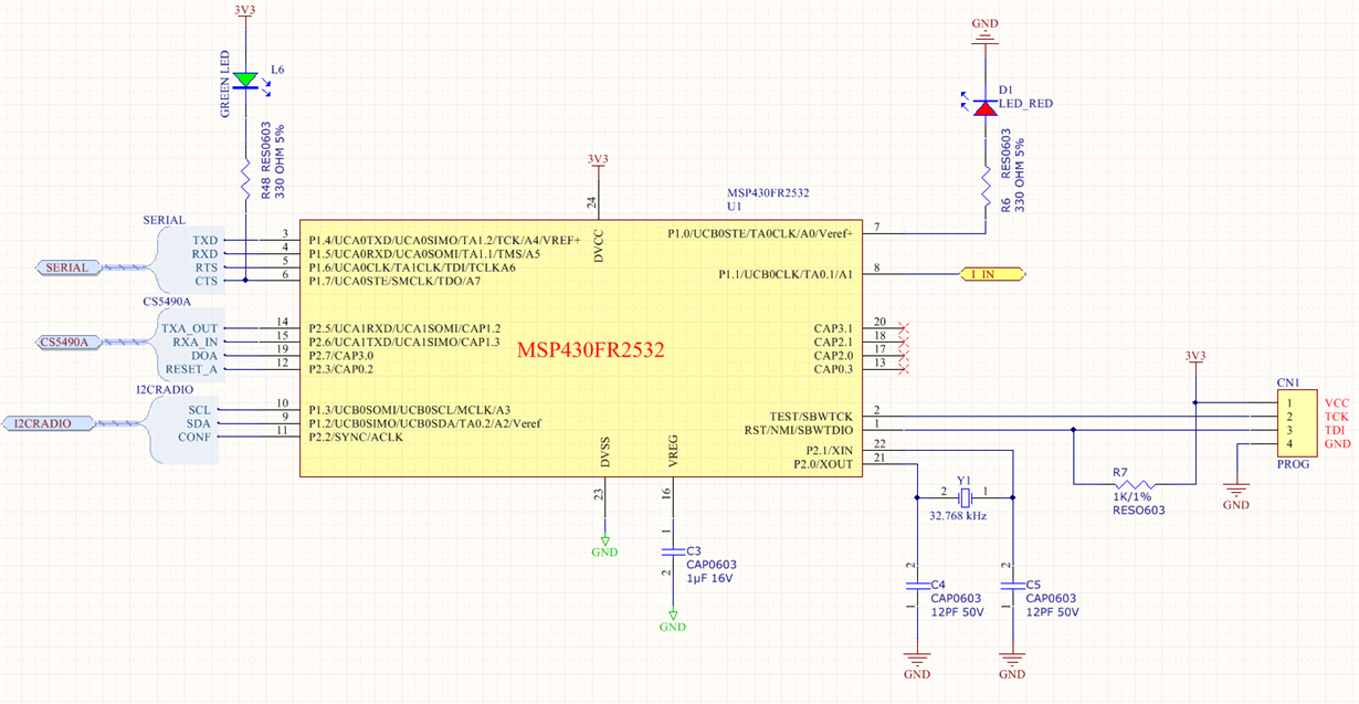
The schematic of core ( I only assembled the chip, capacitors and resistors to minimum setup.  ( OBservation) In schematic the name of chip is 25, the correct is 26.)

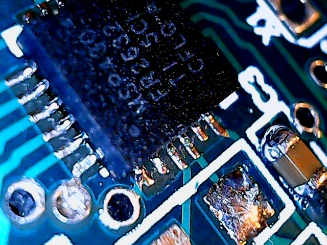
The soldering is perfect without short circuit. 

the voltage is 3.3V in chip. 

Questions:

Can I use the MSP430FR2311 to programmer/debug the MSP430FR2652 ?

Is there some test to detect real problem?

Thank you for attention and have a amazing weekend!

  • The eZ-FET from the MSP-EXP430FR2311 is capable of programming the MSP430FR2632 using the RST, TEST, VCC, and GND lines. Wire lengths should be as short as possible and the RST line should have a 47 kOhm pull-up resistor and 1 nF pull-down capacitor. 1 uF + 100 nF decoupling caps should be populated as close to the DVcc pin as possible.

    Regards,
    Ryan
  • Ryan Brown1 said:
    RST line should have a 47 kOhm pull-up resistor and 1 nF pull-down capacitor.


    This is important for starting device program execution after flashing, irrelevant for flashing when device (and RST line) is under FET control. 47k + 1nF is just disturbance for SBW.

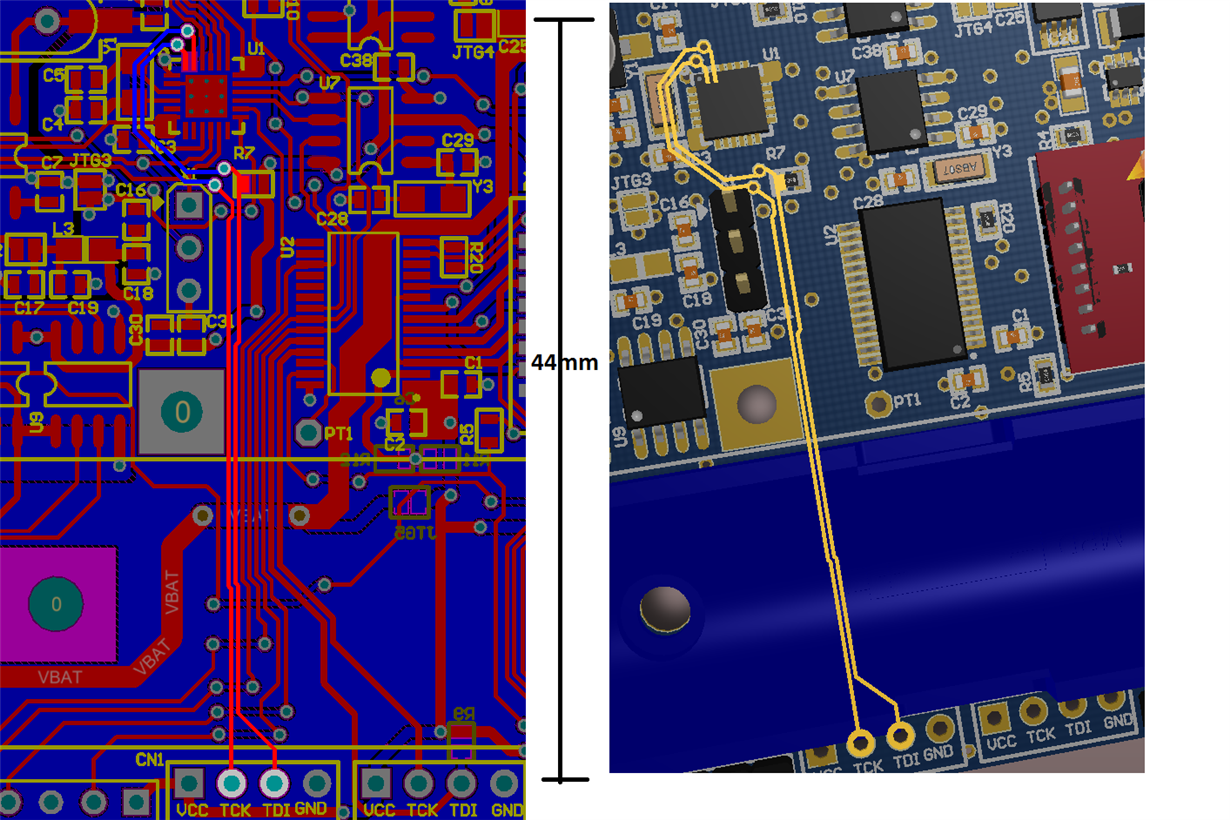
  • I verified the distance between the programmer connection and chip has 44mm.  and Im using a same cable used to program the MSP430G2553. (work perfectly) , however I cant to programmer MSP430FR2632.

    I trying to find one way to test the connection between the lauchpad and MSP430FR2632, but I didnt find. 

    Is there any TI tool only to test and verify the microcontroller. 

     My hardware designed. This is first time that a board with TI fail with me. I trying to find some answer . Thank you

  • Hi Carlos!

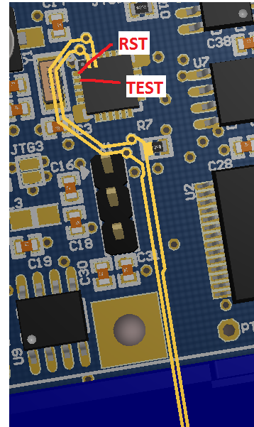
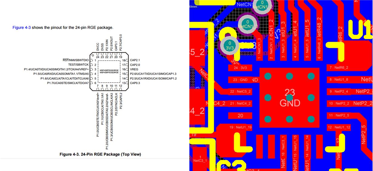
    I may have bad news...from the board layout it looks like your CAD library for the MSP is wrong. Your pins seem to be flipped.

    Note that in the datasheet you always see through the device (TOP VIEW), the pins are not shown from the bottom side.

    The position of the crystal seems to confirm this...it looks like your CAD library was created thinking you are looking at the bottom of the part.

    Unfortunately this means that your PCB is useless ;-\ I hope this is a prototype.

    Dennis

  • Hi Dennis, Thank you, I verified here, my footprint library is wrong.  

    Go to factory again . Impossible Use or save propotype, dense board.  

    I appreciate your attention.  

  • Carlos,

    I'm sorry to see your library footprint resulted in a faulty board design. The MSP430FR2632 quality page contains the correct VQFN CAD/CAE Symbol which can be loaded into Ultra Librarian and exported to your PCB designer (Altium): webench.ti.com/.../MSP430FR2632_RGE_24.bxl

    Regards,
    Ryan

**Attention** This is a public forum