This thread has been locked.

If you have a related question, please click the "Ask a related question" button in the top right corner. The newly created question will be automatically linked to this question.

MSP432 I2S implementation

Hello,

I am trying to implement an I2S bus on a MSP432, following this application note :

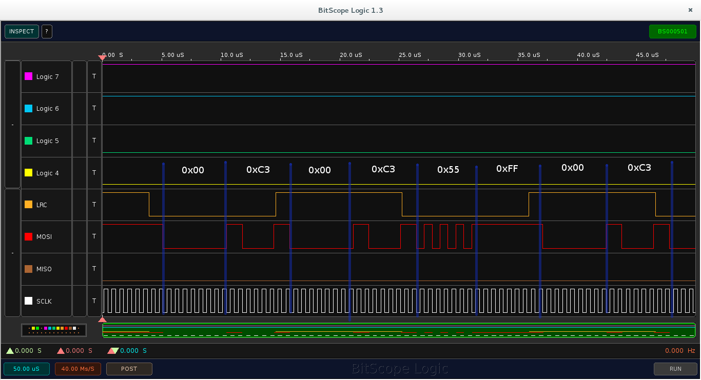
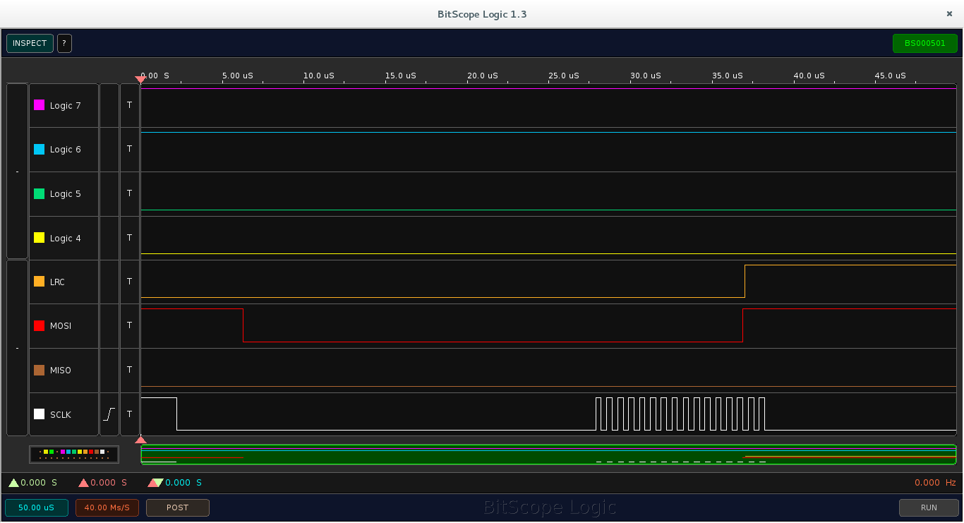
I am now trying to configure the SPI and the DMA to provide a continuous flow of data through the SPI lines. This does not work as expected, the SPI sends 16 clock pulses then stops as you can see on my logic analyser screenshot :

I basically copied then modified the DMA_eusci_I2C_loopback example.

If I place a breakpoint in the DMA interrupt function, the debugger regulary stops in it, but the SPI lines don't show any activity.

Here is my code :

/*************************
 * Libraries
 *************************/
/* DriverLib Includes */
#include "driverlib.h"
/* Audio codec library */
#include "WM8731_Driver.h"
/* Standard Includes */
#include <stdint.h>
#include <stdbool.h>

/************************
 * Peripherals
 ************************/
/* DMA Control Table */
#if defined(__TI_COMPILER_VERSION__)
#pragma DATA_ALIGN(MSP_EXP432P401RLP_DMAControlTable, 1024)
#elif defined(__IAR_SYSTEMS_ICC__)
#pragma data_alignment=1024
#elif defined(__GNUC__)
__attribute__ ((aligned (1024)))
#elif defined(__CC_ARM)
__align(1024)
#endif
static DMA_ControlTable MSP_EXP432P401RLP_DMAControlTable[32];

/* SPI configuration */
const eUSCI_SPI_MasterConfig SPIConfig =
{
		EUSCI_SPI_CLOCKSOURCE_SMCLK,			//SMCLK Clock Source
		12000000,								//SMCLK = 12MHz
		1500000,								//Desired SPI Clock of 1.5MHz
		EUSCI_SPI_MSB_FIRST,					//Data MSB first
		EUSCI_SPI_PHASE_DATA_CAPTURED_ONFIRST_CHANGED_ON_NEXT,	//Rising edge
		EUSCI_SPI_CLOCKPOLARITY_INACTIVITY_LOW,	//SCLK=0 when inactive
		EUSCI_SPI_3PIN							//3-pin SPI
};

/*************************************
 *  Interrupt routines declaration
 *************************************/
void DMA_Interrupt();

/************************************
 * Global variables
 ************************************/
//Digital audio buffers, read/wrote by DMA
int8_t AudioDataIn[4], AudioDataOut[4]={0,1,2,3};
//Audio intermediate buffers
int16_t GtrIn, GtrOut=0;
//Data ready flag, to start audio processing
bool AudioDataReady=false;

/***********************************
 * Main program
 ***********************************/
int main(void)
{

	/* Stop interrupts for initialisation */
	Interrupt_disableMaster();

	/* Halting the Watchdog */
	MAP_WDT_A_holdTimer();

	/***********************************************
	 * Clocking
	 ***********************************************/
	//Pins
	MAP_GPIO_setAsPeripheralModuleFunctionOutputPin(GPIO_PORT_PJ,GPIO_PIN3 | GPIO_PIN4, GPIO_PRIMARY_MODULE_FUNCTION);
	//Setting the external clock frequency
	CS_setExternalClockSourceFrequency(32000,48000000);
	//Starting HFXT in non-bypass mode without a timeout. Before we start
	//we have to change VCORE to 1 to support the 48MHz frequency
	MAP_PCM_setCoreVoltageLevel(PCM_VCORE1);
	MAP_FlashCtl_setWaitState(FLASH_BANK0, 2);
	MAP_FlashCtl_setWaitState(FLASH_BANK1, 2);
	CS_startHFXT(false);
	//Initializing clock signals */
	MAP_CS_initClockSignal(CS_ACLK, CS_LFXTCLK_SELECT, CS_CLOCK_DIVIDER_1);//ACLK=32kHz
	MAP_CS_initClockSignal(CS_MCLK, CS_HFXTCLK_SELECT, CS_CLOCK_DIVIDER_1);//MCLK=48kHz
	MAP_CS_initClockSignal(CS_SMCLK, CS_HFXTCLK_SELECT, CS_CLOCK_DIVIDER_4);//SMCLK=12MHz

	/****************************************************
	 * EUSCI_A3 SPI (for I2S interface)
	 ****************************************************/
	//Pins
	MAP_GPIO_setAsPeripheralModuleFunctionInputPin(GPIO_PORT_P9, GPIO_PIN6, GPIO_PRIMARY_MODULE_FUNCTION);//MISO
	MAP_GPIO_setAsPeripheralModuleFunctionOutputPin(GPIO_PORT_P9, GPIO_PIN5|GPIO_PIN7, GPIO_PRIMARY_MODULE_FUNCTION);//SCLK, MOSI
	MAP_GPIO_setAsOutputPin(GPIO_PORT_P7, GPIO_PIN5);//External counter reset
	MAP_GPIO_setOutputHighOnPin(GPIO_PORT_P7, GPIO_PIN5);//Counter reset pin held high
	//SPI setup
	SPI_initMaster(EUSCI_A3_BASE, &SPIConfig);
	//Enable SPI
	SPI_enableModule(EUSCI_A3_BASE);

    /****************************************************
     * DMA (coupled with SPI to make I2S)
     ****************************************************/
	//Enable DMA module
	MAP_DMA_enableModule();
	MAP_DMA_setControlBase(MSP_EXP432P401RLP_DMAControlTable);
	//Assign channel 6 to EUSCI_A3_TX, channel 7 to EUSCI_A3_RX
	DMA_assignChannel(DMA_CH6_EUSCIA3TX);
	DMA_assignChannel(DMA_CH7_EUSCIA3RX);
	//Set TX transfer
	DMA_setChannelControl(DMA_CH6_EUSCIA3TX | UDMA_PRI_SELECT,
	    UDMA_SIZE_8 | UDMA_SRC_INC_8 | UDMA_DST_INC_NONE | UDMA_ARB_1);
	DMA_setChannelTransfer(DMA_CH6_EUSCIA3TX | UDMA_PRI_SELECT,
	    UDMA_MODE_AUTO, AudioDataOut,
		(void *) MAP_SPI_getTransmitBufferAddressForDMA(EUSCI_A3_BASE),
		4);
	//Set RX transfer
	DMA_setChannelControl(DMA_CH7_EUSCIA3RX | UDMA_PRI_SELECT,
	    UDMA_SIZE_8 | UDMA_SRC_INC_NONE | UDMA_DST_INC_8 | UDMA_ARB_1);
	DMA_setChannelTransfer(DMA_CH7_EUSCIA3RX | UDMA_PRI_SELECT,
	    UDMA_MODE_AUTO,
		(void *) MAP_SPI_getReceiveBufferAddressForDMA(EUSCI_A3_BASE),
		AudioDataOut,
		4);
	//Assign DMA interrupt : INT1 to TX channel
	DMA_assignInterrupt(INT_DMA_INT1, 6);
	//Register interrupt to a defined subroutine
	DMA_registerInterrupt(INT_DMA_INT1, DMA_Interrupt);
	//Flag set by default, so we have to clear it
	DMA_clearInterruptFlag(6);
	//Enable interrupt
	Interrupt_enableInterrupt(INT_DMA_INT1);
	DMA_enableInterrupt(INT_DMA_INT1);
	//Everything is set up, we can enable the two DMA channels
	DMA_enableChannel(6);
	DMA_enableChannel(7);

    /* Interrupts activation */
    Interrupt_enableMaster();

    /* Main program loop */
    while(1)
    {
    	if(AudioDataReady==true)
    	{
    		//Reset flag
    		AudioDataReady=false;

    		/*****************************
    		 * Audio processing
    		 *****************************/
    		//GtrIn : last guitar sample
    		//GtrOut : next sample to be sent to amp

    		GtrOut=0x0001;//Debug

    		/******************************/
    		//Put audio into DMA
    		AudioDataOut[0]=(int8_t)(GtrOut>>8);
    	    AudioDataOut[1]=(int8_t)(GtrOut&0x00FF);
    	}
    }
}

/** Interrupt routines */
/* Completion interrupt for DMA */
void DMA_Interrupt()
{

	//Set flag for audio processing
    AudioDataReady=true;
    //Save new audio data
    GtrIn=((int16_t)AudioDataIn[0]<<8)+(int16_t)(AudioDataIn[1]);

    DMA_clearInterruptFlag(6);

}

I don't understand why SPI sends the first two packets, then suddenly stops ?

Thank you for any help,

David

  • Hello David,

    Let us review your code and we will get back to you. In the meantime, which version of the MSP432 LP are you using??

    Thanks,

    David
  • Hello DavidL, thank you for having a look,

    I am using a MSP432P401R, on the MSP432 Launchpad.

  • David,
    I would recommend changing the mode to 'BASIC' and also changing the receive buffer:

    //Set TX transfer
    MAP_DMA_setChannelControl(DMA_CH6_EUSCIA3TX | UDMA_PRI_SELECT,
    UDMA_SIZE_8 | UDMA_SRC_INC_8 | UDMA_DST_INC_NONE | UDMA_ARB_1);
    MAP_DMA_setChannelTransfer(DMA_CH6_EUSCIA3TX | UDMA_PRI_SELECT,
    UDMA_MODE_BASIC, AudioDataOut,
    (void *) MAP_SPI_getTransmitBufferAddressForDMA(EUSCI_A3_BASE),
    4);
    //Set RX transfer
    MAP_DMA_setChannelControl(DMA_CH7_EUSCIA3RX | UDMA_PRI_SELECT,
    UDMA_SIZE_8 | UDMA_SRC_INC_NONE | UDMA_DST_INC_8 | UDMA_ARB_1);
    MAP_DMA_setChannelTransfer(DMA_CH7_EUSCIA3RX | UDMA_PRI_SELECT,
    UDMA_MODE_BASIC,
    (void *) MAP_SPI_getReceiveBufferAddressForDMA(EUSCI_A3_BASE),
    AudioDataIn,
    4);

    Also, just for reference here is another post which uses the scatter-gather to get Rx and Tx information. I thought that this might provide an interesting way to address the Right/Left Clock.

    e2e.ti.com/.../529109

    Please let me know if this addresses the issue you are seeing and I will also confirm on my side.

    Thanks and Regards,
    Chris
  • Hello Chris,

    Thank you for your answer. I tried to apply the changes you recommended, it made the SPI send 32 bits instead of 16 (and use the right Rx buffer !), which is nice.

    I then tried to re-add the DMA initialization code into the interrupt function, that made the SPI work continuously. I then removed lines one by one to find the necessary ones and remove the others, my DMA interrupt function now looks like this :

    /* Completion interrupt for DMA */
    void DMA_Interrupt()
    {
    	//Set flag for audio processing
        AudioDataReady=true;
        //Save new audio data
        GtrIn=((int16_t)AudioDataIn[0]<<8)+(int16_t)(AudioDataIn[1]);
    
    	//Set TX transfer
    	DMA_setChannelTransfer(DMA_CH6_EUSCIA3TX | UDMA_PRI_SELECT,
    		UDMA_MODE_BASIC, (void *) AudioDataOut,
    		(void *) MAP_SPI_getTransmitBufferAddressForDMA(EUSCI_A3_BASE),
    		4);
    	//Set RX transfer
    	DMA_setChannelTransfer(DMA_CH7_EUSCIA3RX | UDMA_PRI_SELECT,
    		UDMA_MODE_BASIC,
    		(void *) MAP_SPI_getReceiveBufferAddressForDMA(EUSCI_A3_BASE),
    		(void *) AudioDataIn,
    		4);
    	//Everything is set up, we can enable the two DMA channels
    	DMA_enableChannel(6);
    	DMA_enableChannel(7);
    
        //Clear interrupt flag
        DMA_clearInterruptFlag(6);
    }
    

    Now my SPI sends continuously. To check that the bytes were sent in the right order, I gave my output buffer the following value :

    int8_t AudioDataOut[4]={0x00,0xC3,0x55,0xFF};

    So the 4 bytes to send are easy to recognize. But here is what it actually sends : (look at the MOSI line)

    It should send : 0x00 - 0xC3 - 0x55 - 0xFF - 0x00 - 0xC3 - ...

    And it sends : 0x00 - 0xC3 - 0x00 - 0xC3 - 0x55 - 0xFF - 0x00 - 0xC3 ...

    It looks like the DMA sends the two first bytes twice before they send the two last bytes !

    (and the LRC is dephased, I'll fix this later by resetting the counter ...)

    About the Scatter-gather method, I've seen that it was used for segmented memory areas, which is not the case here ... Would it really help ?


    EDIT : I just had a look on the scatter-gather example you gave ... Looks perfect ! I will give it a try.

    Thank you for your help,

    David

  • David,

        I will need to go back into the API and try to understand why the first set might be repeated.  One thing to be careful of is that the TX trigger happens after the data is moved from the buffer into the shift register while the RX trigger happens after the data has been shifted in (and the TX shifted out).  It is possible that you are entering the ISR and writing to the DMA registers while the RX is still being performed.  It may be more intuitive if the ISR is based upon the RX because then you know that the SPI communication is complete.

        Additionally, I typically do not use the driverlib calls in the ISR for the DMA update.  There is some overhead associated with the call and you only really need to update the control register.  See the following example:

    /* Disabling DMA Channel 0 */
    MAP_DMA_disableChannel(0);
    // MAP_DMA_setChannelControl((UDMA_PRI_SELECT | DMA_CH0_TIMERA0CCR0),
    // UDMA_SIZE_8 | UDMA_SRC_INC_NONE | UDMA_DST_INC_8 | UDMA_ARB_1024);
    // MAP_DMA_setChannelTransfer((UDMA_PRI_SELECT | DMA_CH0_TIMERA0CCR0), UDMA_MODE_BASIC, (void *)(0x40004C01),
    // destinationArray, SAMPLE_SIZE);
    MSP_EXP432P401RLP_DMAControlTable[0].control &= 0xFFFFC000;
    MSP_EXP432P401RLP_DMAControlTable[0].control |= ((SAMPLE_SIZE-1)<<4) + UDMA_MODE_BASIC;

    /* Enabling DMA Channel 0 */
    MAP_DMA_enableChannel(0);

    I am still looking into the I2S implementation.  Ideally I would like to get rid of the external hardware and do this completely within the MSP432.  My concern is trying to stream large amount of I2S without having to continually update the DMA.  I hope to have some preliminary examples soon, let me know if you have any codecs you recommend.

    Regards,

    Chris

  • Using RX instead of TX solved the bytes-disorder issue. Thank you for the advice about the control register, it's good optimization.

    It almost works, the bytes are sent in the right order. The SPI clock is not contiguous, but it might not be an issue, the most important being to synchronize the transmission over the sampling frequency. I did this using a timer. The DMA interrupt only disables the DMA, the timer interrupt sets up the DMA control register and enables the DMA.

    It looks like this :

    The only issue is the external counter (sourcing LRC), which is does not start from zero for any reason (I reset it at the beginning of the program). I will try to manage this pin without the external hardware, with the scatter-gather DMA, or with an internal timer used as a counter (that may be simpler ?).

    By the way, I'm using a WM8731L codec, which I have chosen because the following board exists : http://www.mikroe.com/add-on-boards/audio-voice/audio-codec-proto/

    Thank you for your help,

    David

**Attention** This is a public forum