This thread has been locked.

If you have a related question, please click the "Ask a related question" button in the top right corner. The newly created question will be automatically linked to this question.

Best Function for external adc

Other Parts Discussed in Thread: MSP430G2553, MSP430F2013

Hi Everybody,

I have msp430g2553 with launchpad and i'm working with CCS

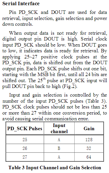
I want to know what functions (i2c,spi,uart etc.) can i use for communicating with HX711 Dual-Channel Weighing Sensor Module?

it has a built-in ADC.

hx711 has 4 pins:

1. vcc

2. gnd

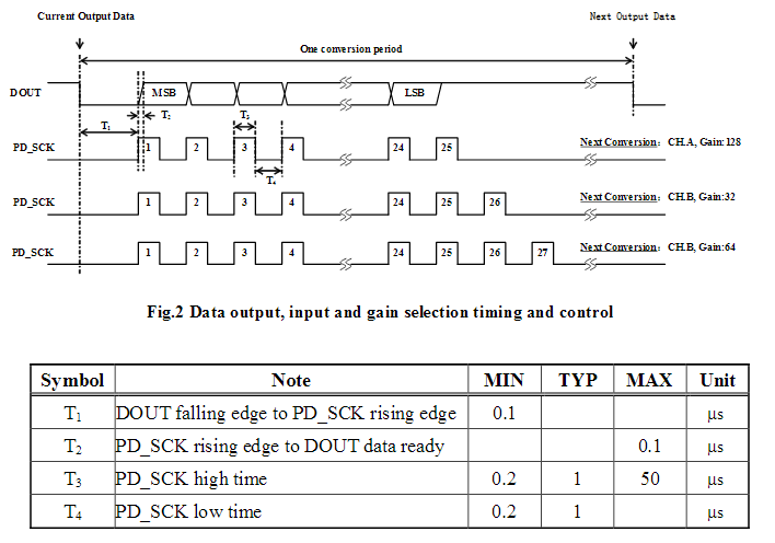
3. dt - for data transfer

4. sck - for clock

it doesn't contains slave address so i2c isn't relevant.

Thank you

  • The HX711's interface is some kind of special. It has no DIN pin and uses additional clock cycles to talk to the device. You have 24 clock pulses for the result which can be retrieved via SPI, but then you have to apply one, two or three additional pulses to select the next input channel and the gain. This cannot be done by the USCI module. The USI module on a MSP430F2013 could do that because it let's you select the number of bits you want to send. Anyway, with an USCI module you will have to write something on your own. You can use SPI for the first three bytes and then switch over to bitbanging or you can bitbang the whole data. Or use a second pin of the MSP and connect SPI clock with a resistor to the HX711. Then connect the second pin directly to the CLK of the HX711 so it can override the SPI clock level.

    Dennis

  • Hi,

    I'm using bit banging for the whole data

    i tried first to get the first 24 bits but i don't get a logic answer (get all 0 or all 1)

    I didn't remove any of the jumpers.

    here's my code (please refer to bitbang_data_in function )

    #include <msp430.h> 
    
    #define DATA_OUT_PORT    P1OUT
    #define DATA_OUT_PIN     BIT5
    
    #define DATA_IN_PORT    P1IN
    #define DATA_IN_PIN     BIT5
    
    #define CLOCK_OUT_PORT   P1OUT
    #define CLOCK_OUT_PIN    BIT3
    
    /*
     * main.c
     */
    
    void bitbang_data_out( unsigned char data );
    unsigned char  bitbang_data_in( );
    
    int main(void) {
        WDTCTL = WDTPW | WDTHOLD;	// Stop watchdog timer
        CLOCK_OUT_PORT &= ~CLOCK_OUT_PIN;
        P1DIR |= DATA_OUT_PIN;
    
        bitbang_data_in();
    	while(1);
    
    
    	return 0;
    }
    
    void bitbang_data_out( unsigned char data )
    {
    	unsigned char i;
    
      for( i = 0; i < 8; i++ )
      {
        if( data & 0x80 )
        {
          DATA_OUT_PORT |= DATA_OUT_PIN;
        }
        else
        {
          DATA_OUT_PORT &= ~DATA_OUT_PIN;
        }
    
        CLOCK_OUT_PORT |=  CLOCK_OUT_PIN;
        CLOCK_OUT_PORT &= ~CLOCK_OUT_PIN;
    
        data <<= 1;
      }
    }
    
    unsigned char bitbang_data_in()
    {
    	unsigned char data[3];
    	unsigned char  i,j=2;
    
    	for(j = 0; j < 3; j++)
    	{
    		for( i = 0; i < 8; i++ )
    		{
    			if(DATA_IN_PORT & DATA_IN_PIN)
    			{
    				data[2-j] |= 0x01;
    			}
    
    			CLOCK_OUT_PORT |= CLOCK_OUT_PIN;
    			CLOCK_OUT_PORT &= ~CLOCK_OUT_PIN;
    
    			data[2-j] <<= 1;
    		}
    	}
    	return data[0];
    }
    

  • I don't see any necessity for an input and output function since the HX711 only delivers data when requested by the microcontroller, but it will never receive anything. It only counts additional clock pulses.

    Data is ready when DOUT goes low, clock should idle low, data is changed at the rising edge and captured at the falling one.

  • Joe Shoshana said:
    P1DIR |= DATA_OUT_PIN;

    Clock needs to be an output as well.

  • Thank you
    The clock as an output solve my problem
    thank you so much for your time

**Attention** This is a public forum