This thread has been locked.

If you have a related question, please click the "Ask a related question" button in the top right corner. The newly created question will be automatically linked to this question.

Interrupt Driven I2C Design for Wii Nunchuck

Other Parts Discussed in Thread: MSP430FR4133, MSP430WARE, MSP430G2231

Hello,

I  am currently using a MSP430FR4133 and trying to use interrupts to interface with a wii nunchuck.  I have referenced heavily from 2 different I2C examples provided from MSP430Ware (msp430fr413x_euscib0_i2c_10.c and msp430fr413x_euscib0_i2c_15.c) and reproduced the following code attached.  

/* --COPYRIGHT--,BSD_EX
 * Copyright (c) 2014, Texas Instruments Incorporated
 * All rights reserved.
 *
 * Redistribution and use in source and binary forms, with or without
 * modification, are permitted provided that the following conditions
 * are met:
 *
 * *  Redistributions of source code must retain the above copyright
 *    notice, this list of conditions and the following disclaimer.
 *
 * *  Redistributions in binary form must reproduce the above copyright
 *    notice, this list of conditions and the following disclaimer in the
 *    documentation and/or other materials provided with the distribution.
 *
 * *  Neither the name of Texas Instruments Incorporated nor the names of
 *    its contributors may be used to endorse or promote products derived
 *    from this software without specific prior written permission.
 *
 * THIS SOFTWARE IS PROVIDED BY THE COPYRIGHT HOLDERS AND CONTRIBUTORS "AS IS"
 * AND ANY EXPRESS OR IMPLIED WARRANTIES, INCLUDING, BUT NOT LIMITED TO,
 * THE IMPLIED WARRANTIES OF MERCHANTABILITY AND FITNESS FOR A PARTICULAR
 * PURPOSE ARE DISCLAIMED. IN NO EVENT SHALL THE COPYRIGHT OWNER OR
 * CONTRIBUTORS BE LIABLE FOR ANY DIRECT, INDIRECT, INCIDENTAL, SPECIAL,
 * EXEMPLARY, OR CONSEQUENTIAL DAMAGES (INCLUDING, BUT NOT LIMITED TO,
 * PROCUREMENT OF SUBSTITUTE GOODS OR SERVICES; LOSS OF USE, DATA, OR PROFITS;
 * OR BUSINESS INTERRUPTION) HOWEVER CAUSED AND ON ANY THEORY OF LIABILITY,
 * WHETHER IN CONTRACT, STRICT LIABILITY, OR TORT (INCLUDING NEGLIGENCE OR
 * OTHERWISE) ARISING IN ANY WAY OUT OF THE USE OF THIS SOFTWARE,
 * EVEN IF ADVISED OF THE POSSIBILITY OF SUCH DAMAGE.
 *
 *******************************************************************************
 *
 *                       MSP430 CODE EXAMPLE DISCLAIMER
 *
 * MSP430 code examples are self-contained low-level programs that typically
 * demonstrate a single peripheral function or device feature in a highly
 * concise manner. For this the code may rely on the device's power-on default
 * register values and settings such as the clock configuration and care must
 * be taken when combining code from several examples to avoid potential side
 * effects. Also see www.ti.com/grace for a GUI- and www.ti.com/msp430ware
 * for an API functional library-approach to peripheral configuration.
 *
 * --/COPYRIGHT--*/
//******************************************************************************
//  MSP430FR413x Demo - Toggle P1.0 using software
//
//  Description: I2C interface with Wii Nunchuck
//  By default, FR413x select XT1 as FLL reference.
//  If XT1 is present, the PxSEL(XIN & XOUT) needs to configure.
//  If XT1 is absent, switch to select REFO as FLL reference automatically.
//  XT1 is considered to be absent in this example.
//  ACLK = default REFO ~32768Hz, MCLK = SMCLK = default DCODIV ~1MHz.
//
//                                /|\  /|\
//               Wii Nunchuck      10k  10k     MSP430FR4133
//                   slave         |    |        master
//             -----------------   |    |   -----------------
//            |              SDA|<-|----|->|P5.2/UCB0SDA     |
//            |                 |  |       |                 |
//            |                 |  |       |                 |
//            |              SCL|<-|------>|P5.3/UCB0SCL     |
//            |                 |          |             P1.0|--> LED
//
//   Jerry Leung
//   Texas Instruments Inc.
//   October 2016
//   Built with Code Composer Studio v6.1.3
//******************************************************************************
#include <msp430.h>

	// Slave address for wii nunchuck is 0x52
	// For black Wii nunchuck:
	//		Initializing 1st register: 0xF0 and 0x55
	//		Initializing 2nd register: 0xFB and 0x00
	// For white Wii nunchuck:
	//		Send 0x40, 0x00, followed by 0x00

unsigned char SlaveAddress = 0x52;						// Slave address of wii nunchuck
unsigned char TXData[]= {0xF0,0x55,0xFB,0x00};        	// Handshake TX data
volatile unsigned char nunchuck_data[6] = {0, 0, 0, 0, 0, 0};		// data from nunchuk
														// Declared volatile because there will be multiple
														// receive data as this operates
unsigned int counter = 0;

// Need to check if MSP430 has internal functions like end of array instead of having to hard code counters below
unsigned char TXByteCtr;								// Number of handshake bytes. Set at 4
unsigned char TXPointer;								// Position of TXData array. Start with TXData[0]
unsigned char RXByteCtr;								// Number of bytes of data from wii nunchuck. Set at 6
unsigned char RXPointer;								// Postion of nunchuck_data

void init()
{
	WDTCTL = WDTPW | WDTHOLD;               // Stop watchdog timer

    // Configure GPIO
    P1OUT &= ~BIT0;                         // Clear P1.0 output latch
    P1DIR |= BIT0;                          // For LED
    P5SEL0 |= BIT2 | BIT3;                  // I2C pins

    // Disable the GPIO power-on default high-impedance mode to activate
    // previously configured port settings
    PM5CTL0 &= ~LOCKLPM5;
}

void i2c_init()
{
    // Configure USCI_B0 for I2C mode
	// For TX
    UCB0CTLW0 |= UCSWRST;                   // put eUSCI_B in reset state
    UCB0CTLW0 |= UCMODE_3 | UCMST | UCSYNC; // I2C mode, Master mode, sync

    // For RX
    UCB0CTLW1 |= UCASTP_2;                  // Automatic stop generated after UCB0TBCNT is reached
    UCB0TBCNT = 0x0006;                     // number of bytes to be received  // Wii nunchuck receives 6 bytes of data

    UCB0BRW = 0x0008;                       // baudrate = SMCLK / 8
    UCB0CTLW0 &=~ UCSWRST;                  // Release eUSCI_B reset state

    UCB0IE |= UCTXIE0 | UCRXIE | UCNACKIE | UCBCNTIE; // Interrupt enables. Transmit | Receive | NACK | Byte Counter

}

void nunchuck_init()
{
    __delay_cycles(1);                   // Delay between transmissions
	UCB0I2CSA = SlaveAddress;				// Address of the slave device, wii nunchuk
	TXByteCtr = 4;							// Load TX byte counter
											// There are 4 bytes for handshake with a black wii nunchuck
	TXPointer = 0;							// Start by sending the 1st entry in the array
	while (UCB0CTLW0 & UCTXSTP);            // Ensure stop condition got sent
    UCB0CTLW0 |= UCTR | UCTXSTT;            // I2C TX, start condition
    __bis_SR_register(LPM0_bits | GIE);     // Enter LPM0 w/ interrupts. Remain in LPM0 until all data is TX'd
    										// Wait for transmit interrupt flag UCTXIFG0 to set
    										// which indicates that the transmit buffer UCBxTXBUF is empty
    										// Low power mode will exit after all bytes are transmitted
}

void nunchuck_read()
{
    __delay_cycles(1);                   // Delay between transmissions
    // Don't need to set the slave address again
    UCB0I2CSA = SlaveAddress;				// Address of the slave device, wii nunchuk
    UCB0IE &= ~UCTXIE0;						// Disable transmit interrupt
    UCB0IE |= UCRXIE | UCNACKIE | UCBCNTIE; // Interrupt enables. Receive | NACK | Byte Counter
	RXByteCtr = 6;							// Load RX byte counter
											// There are 6 bytes of data from wii nunchuck
    while (UCB0CTLW0 & UCTXSTP)
    {										// Ensure stop condition got sent
    	P1OUT ^= BIT0;                      // Toggle P1.0 using exclusive-OR;
    	_delay_cycles(1);
    }
//    while (UCB0CTL1 & UCTXSTP);            // Ensure stop condition got sent
    UCB0CTLW0 |= UCTXSTT;            		// I2C start condition, UCTR not set in order to receive
//    UCB0CTL1 |= UCTXSTT;            		// I2C start condition, UCTR not set in order to receive
    __bis_SR_register(LPM0_bits|GIE);   	// Enter LPM0 w/ interrupt
											// Wait for receive interrupt flag UCRXIFG0 to set
											// which indicates that a char is received and loaded
    										// into the receive buffer UCBxRXBUF
											// Low power mode will exit after all bytes are received
}

int main(void)
{

	init();
	i2c_init();
	nunchuck_init();

    while(1)
    {
    	nunchuck_read();					// Read data from nunchuck and store into nunchuck_data array
    	__delay_cycles(1);             	// Delay for 1000*(1/MCLK)=0.001s
    }
}

// Interrupt Handlers and service routines ISR
#if defined(__TI_COMPILER_VERSION__) || defined(__IAR_SYSTEMS_ICC__)
#pragma vector = USCI_B0_VECTOR
__interrupt void USCIB0_ISR(void)
#elif defined(__GNUC__)
void __attribute__ ((interrupt(USCI_B0_VECTOR))) USCIB0_ISR (void)
#else
#error Compiler not supported!
#endif
{
  switch(__even_in_range(UCB0IV, USCI_I2C_UCBIT9IFG))
  {
        case USCI_NONE:          break;               	// Vector 0: No interrupts break;
        case USCI_I2C_UCALIFG:   break;				  	// Vector 2: ALIFG
        case USCI_I2C_UCNACKIFG:					  	// Vector 4: NACKIFG
            UCB0CTL1 |= UCTXSTT;                      	// resend start if NACK, I2C start condition
          break;
        case USCI_I2C_UCSTTIFG:  break;               	// Vector 6: STTIFG break;
        case USCI_I2C_UCSTPIFG:  break;               	// Vector 8: STPIFG break;
        case USCI_I2C_UCRXIFG3:  break;               	// Vector 10: RXIFG3 break;
        case USCI_I2C_UCTXIFG3:  break;               	// Vector 14: TXIFG3 break;
        case USCI_I2C_UCRXIFG2:  break;               	// Vector 16: RXIFG2 break;
        case USCI_I2C_UCTXIFG2:  break;               	// Vector 18: TXIFG2 break;
        case USCI_I2C_UCRXIFG1:  break;               	// Vector 20: RXIFG1 break;
        case USCI_I2C_UCTXIFG1:  break;               	// Vector 22: TXIFG1 break;
        case USCI_I2C_UCRXIFG0:               			// Vector 24: RXIFG0
        if (RXPointer < RXByteCtr)						// Check if counter limit has reached
        	{
        	nunchuck_data[RXPointer] = UCB0RXBUF;       // Get RX data
        	RXPointer++;								// Increment RXPointer for the next incoming byte
        	}
        else											// Counter limit has reached and all data has been received
        {
        	RXPointer = 0;								// ResetRXPointer to prevent out of bounds memory access
        												// Probably not needed but just in case
            __bic_SR_register_on_exit(LPM0_bits); 		// Exit LPM0
        }
        	break;

        case USCI_I2C_UCTXIFG0:							// Vector 26: TXIFG0
        	// Transmit interrupt flag, TX buffer UCBxTXBUF is empty and next byte can be loaded
        if (TXPointer < TXByteCtr)                      // Check if counter limit has reached
           {
            UCB0TXBUF = TXData[TXPointer];            	// Load TX buffer
            TXPointer++;								// Increment TXPointer for the next data in the array
           }
        else											// Counter limit has reached and all data has been transmitted
           {
            TXPointer = 0;								// Reset TXPointer to prevent out of bounds memory access
            											// Probably not needed but just in case
        	UCB0CTLW0 |= UCTXSTP;                     	// I2C stop condition
            UCB0IFG &= ~UCTXIFG;                      	// Clear USCI_B0 TX int flag
            __bic_SR_register_on_exit(LPM0_bits);   // Exit LPM0 and disable interrupts
           }
          break;
        case USCI_I2C_UCBCNTIFG:						// Vector 28: BCNTIFG
        	// Btye counter interrupt. Flag is set when the byte counter value reaches the value
        	// defined in UCBxTBCNT (UCB0TBCNT) and UCASTPx = 01 or 10.
            P1OUT ^= BIT0;                        		// Toggle LED on P1.0
        	break;
        case USCI_I2C_UCCLTOIFG: break;               	// Vector 30: clock low timeout
        case USCI_I2C_UCBIT9IFG: break;               	// Vector 32: 9th bit
        default: break;
  }
}

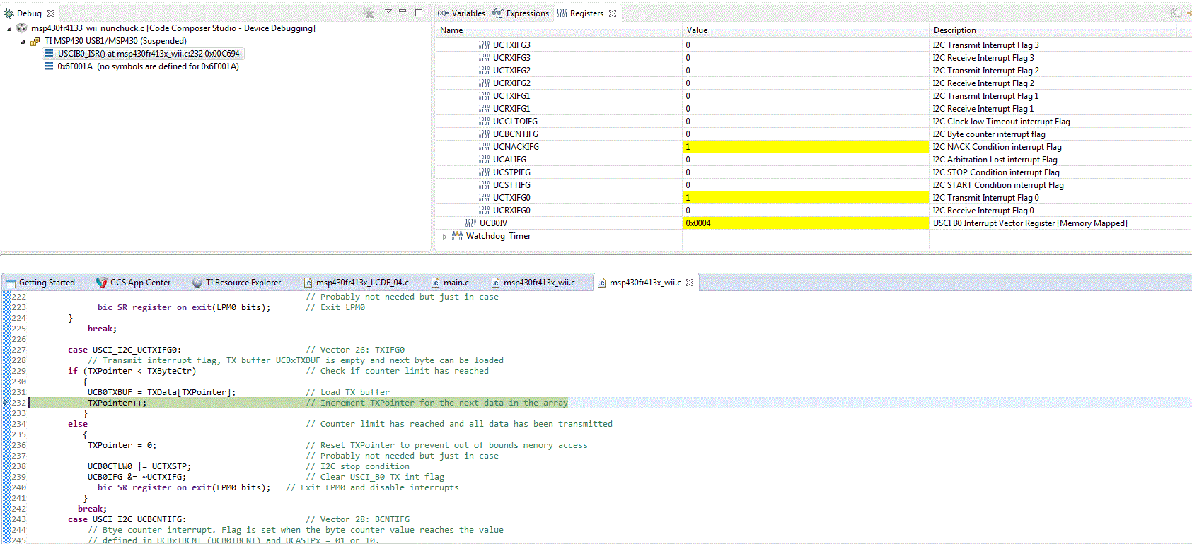
However, as I attempt to run the code, it seems to hang sometimes when I enter LPM0 during TX.  Other times it gets through it but hangs as I attempt to read it.  What I want to verify is whether or not this is a code issue or a hardware connection issue.  

As I am running out of ideas, any help on this would be greatly appreciated.

Thanks and best regards,

Jerry Leung

  • Hello Jerry,

    What actual slave device are you connecting to? At what line does the code get stuck? Can you provide logic analyzer or oscilloscope screenshots that show a break in communication (NACK, clock stretch, or otherwise)? The code examples you've merged together are not completely congruent, for example you set the UCASTP_2 bit in UCB0CTLW1 from the receive example yet you also manually send a stop condition after finished transmitting. The slave address and interrupt enable bits are re-initialized inside of every read function unnecessarily. You also never write the register number that you want to read from after initialization, on some slave devices it will continue to increment the register address until an overflow or invalid address occurs. You also never use while loops to make sure that the buffer is clear before filling it with new data. This all to say that there are several changes and debugging steps that need to be made to the current code.

    e2e.ti.com/.../msp-i2c-getting-started-guide

    Regards,
    Ryan
  • Hello Ryan,

    Thank you very much for your response and feedback. You suggestions provides a very good starting point to help debug my code.

    Just to dive deeper into what you have mentioned, I do have a couple follow up questions that I hope can help clear up my understanding.

    1) When setting the UCASTP_2 for automatic stop conditions,  I specify the UCBOTBCNT to be 6 bytes for that's the number of bytes I would be receiving from the Wii nunchuck.  However, I only transmit 4 bytes to initialize the device.  Therefore, should I not set UCASTP_2 bit altogether and manually send a stop condition every time?

    2) For the other things you mentioned, such as register number to read from after initialization, and while loops to make sure the buffer is clear, I might just be ignorant but I don't see it in the example codes msp430fr413x_euscib0_i2c_10.c and  msp430fr413x_euscib0_i2c_15.c from MSPWare.  Are there other MSPFR4133 examples that can help illustrate these points? Having examples is quite reassuring but if there are none I can attempt to implement them.

    The actual slave device is the black Wii nunchuck and I have SDA and SCL connected to P5.2/UCB0SDA and P5.3/UCB0SCL respectively with 10k pull up resistors.  I am also using the 3.3V and gnd from the launchpad to power and ground the nunchuck.

    As for where the code hangs I now believe it is as you described: 

    "You also never write the register number that you want to read from after initialization, on some slave devices it will continue to increment the register address until an overflow or invalid address occurs."

    Since it seems that when I first try to run the code after reset it enters the nunchuck_read() function but fails to trigger the USCI_I2C_UCRXIFG0 interrupt flag. (Currently it actually enters the USCI_I2C_UCTXIFG0 subroutine before it eventually hangs)

    I will attempt to correct my code with the changes you described but if you have some insights to the couple questions above it will be a tremendous help.

    Thanks and best regards,

    Jerry Leung 

  • Jerry,

    1) Either use the automatic stop for both or neither, using UCB0TBCNT to differentiate between the number of send/receives. Alternatively set UCASTP_2 only when initializing for receiver mode and make sure to not have it being used in transmit mode.

    2) The while loops referred to are not a big deal considering the ISRs being used and are not causing your communication issues. Everyone knows what a Wii nunchuck is but my question refers to the actual I2C slave device inside the nunchuck that you are attempting to communicate with. I wouldn't be surprised to see MSP430 + nunchuck example code already provided by the online community. If you make it past nunchuck_init and on to nunchuck_read then your transmissions are being acknowledged by the slave but it is failing to reply based on the commands being given to it.

    BIG HINT: You never physically reset UCTR when attempting to read, therefore you are still setting the R/W bit low for transmission to the slave instead of reception. msp430fr413x_euscib0_i2c_10.c never implements UCB0CTLW1 &= ~UCTR; since the UCTR bit is never sent in the first place. In here lies the danger of combining example code.

    Regards,
    Ryan
  • Hi Ryan,

    Thanks for all the help so far.  Currently I broke up i2c_init() and created a new function read_init() which would take place after nunchuck_init(), which will reset the UCTR bit and set the automatic stop for receive.  My plan is to set UCASTP_2 only when initializing for receiver mode.

    void read_init()

    {

    // Configure USCI_B0 for I2C mode
    // For RX // Setup for after handshake TX to receive data
    UCB0CTLW0 |= UCSWRST;                                                       // put eUSCI_B in reset state
    UCB0CTLW1 |= UCASTP_2;                                                      // Automatic stop generated after UCB0TBCNT is reached
    UCB0TBCNT = 0x0006;                                                              // number of bytes to be received // Wii nunchuck receives 6 bytes of data
    UCB0CTLW0 &= ~UCTR;                                                            // Reset R/W bit to low for receive
    UCB0CTLW0 &=~ UCSWRST;                                                   // Release eUSCI_B reset state

    }

    Unfortunately it still seems to hang when it enters LMP0_bits with GIE in nunchuck_read(). It seems that it never receives a USCI_I2C_UCRXIFG0 flag.

    However I am now having suspicion that I am not correctly transmitting the handshake protocol in nunchuck_init() to begin with. As I step through the code in the debugger, I noticed that as I am transferring bytes while in the USCI_I2C_UCTXIFG0 routine, I get a NACK interrupt flag, in which case I send the I2C start condition again similar to the example code.

    case USCI_I2C_UCNACKIFG:                            // Vector 4: NACKIFG

    UCB0CTL1 |= UCTXSTT;                           // resend start if NACK, I2C start condition

    break;

    I not entirely sure and please correct me if my assumption is wrong, am I clearing the buffer and trying to transmit the next byte even though the wii nunchuck has not acknowledged the data?   I realized now as I was following the state machine diagram in the user guide (Figure 23-12) that the UCBxTXBUF is discarded when UCNACKIFG = 1. If this is the case, is this a hardware set up issue or is this the while loop issue you mentioned in the beginning?

    I have also been trying to reference example code using the MSP430 + nunchuck but I have been unable to find one that uses interrupt vectors.  The closest one I have been referencing from interfaces the MSP430G2231 with the wii nunchuck and servo motors but it uses USI I2C instead of eUSCI. 

    Madox-Kart (was weeboat) for MSP430 (msp430g2231)

    I tried to decipher this code previously to understand what you mean by writing to the register number to read from and I did note that this example sends a write byte command 0xA5 (slave address 0x52 with the LSB set to high for read) prior to reading from the nunchuck.  However, I don't know if I need to do something similar because it seems that the way I2C is setup with the MSP430FR4133 is different since I have the slave address stored in UCB0I2CSA and UCTR bit to set to read prior to sending the start condition.

    As for the actual I2C device do you mean along the lines as to what microcontroller is in the wii nunchuck? I tried searching for it but couldn't really find much aside from documentations on interfacing with it. 

    Wii Nunchuck Interface: http://free-electrons.com/labs/doc/nunchuk.pdf

    Sorry to keep bombarding with questions but thank you so much for all the help,

    Jerry


  • The USI code you referred to will help very little with your eUSCI interface. You still need to prove that UCTR is cleared for your read function, otherwise you are trying to read from the slave device after sending the R/W bit low (transmission) and it becomes obvious as to why you are getting a NACK condition. The slave expects a command from the master and the master expects data from the slave, therefore nothing happens.

    Regards,
    Ryan

**Attention** This is a public forum