Hello! I'm using a MSP-EXP432P401R Rev. 2.0 Launchpad to program an AD9833 programmable waveform generator. The problem is that I cannot get it to generate anything.
My SPI configuration is the following (SPI mode 3 with 1 MHz clock):
eUSCI_SPI_MasterConfig config =
	{
		EUSCI_B_SPI_CLOCKSOURCE_SMCLK,
		6000000,
		1000000,
		EUSCI_B_SPI_MSB_FIRST,
		EUSCI_B_SPI_PHASE_DATA_CHANGED_ONFIRST_CAPTURED_ON_NEXT,
		EUSCI_B_SPI_CLOCKPOLARITY_INACTIVITY_HIGH,
		EUSCI_B_SPI_3PIN
	};
	// ----Configure SPI Pins are UCB0 on P1.5, P1.6
	// Pin 1.5 = UCB0_SPI_CLK
	MAP_GPIO_setAsPeripheralModuleFunctionOutputPin( GPIO_PORT_P1, GPIO_PIN5, GPIO_PRIMARY_MODULE_FUNCTION);
	// Pin 1.6 = UCB0_SPI_SIMO
	MAP_GPIO_setAsPeripheralModuleFunctionOutputPin( GPIO_PORT_P1, GPIO_PIN6, GPIO_PRIMARY_MODULE_FUNCTION);
	MAP_SPI_initMaster(EUSCI_B0_BASE, &config);
	MAP_SPI_enableModule(EUSCI_B0_BASE);
I've used the driver provided on the Analog Devices website and I've closely followed the initialization procedure example described in the application note AN-1070.
This is my initialization:
MAP_GPIO_setAsOutputPin(ADI_CS_PORT, ADI_CS_PIN);
MAP_GPIO_setOutputHighOnPin(ADI_CS_PORT, ADI_CS_PIN);
AD9833_SetRegisterValue(AD9833_B28 | AD9833_REG_CMD | AD9833_RESET); // 0x2100
AD9833_SetFrequency(AD9833_REG_FREQ0, 0x10C7); // 400 Hz; 0x50C7, 0x4000
AD9833_SetPhase(AD9833_REG_PHASE0,0x00); // 0xC000
AD9833_SetRegisterValue(AD9833_B28); // 0x2000
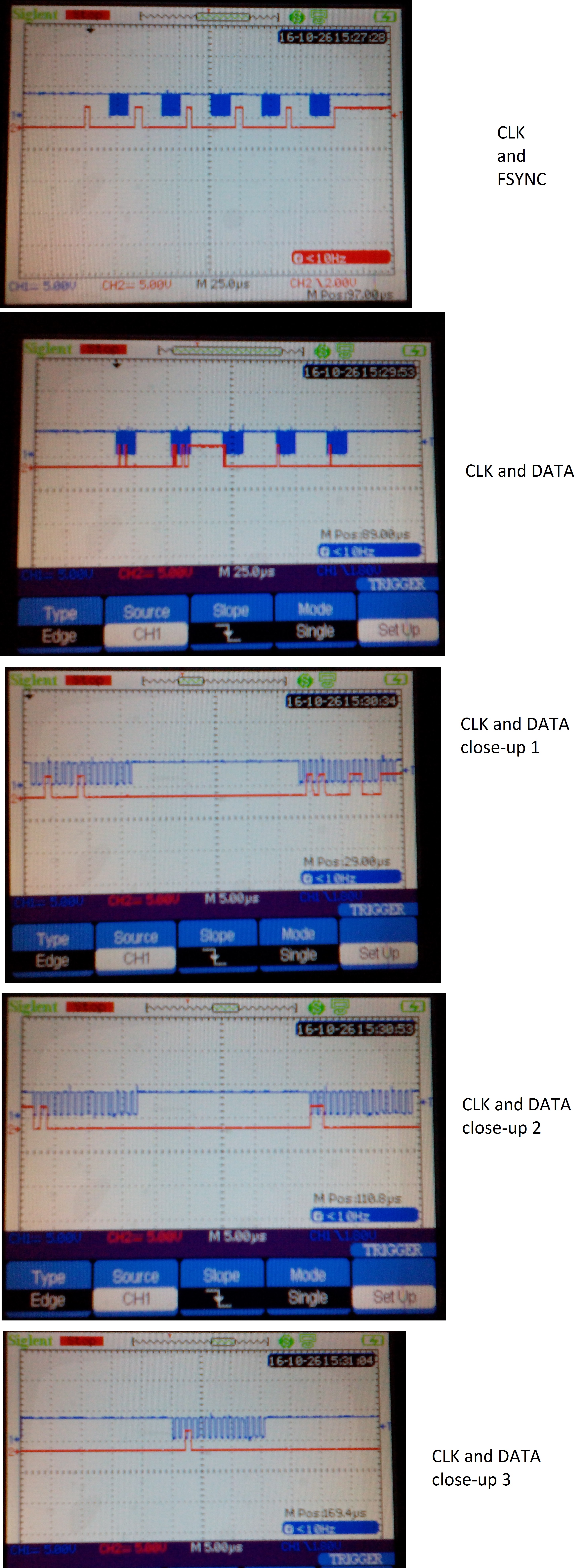
I've checked the SPI waveforms and I can confirm that the data is transmitted as described in the application note. I have attached my schematic and screen captures. From the captures you can see that the data is transmitted correctly (I used delays of a few microseconds). In the schematic, at DDS_Vout I get a DC voltage, around 1,1 V.
Does anybody have an idea about what could be the problem?