This thread has been locked.

If you have a related question, please click the "Ask a related question" button in the top right corner. The newly created question will be automatically linked to this question.

UART RECIEVE NOT WORKING

Other Parts Discussed in Thread: MSP430G2553

Hi Everybody,

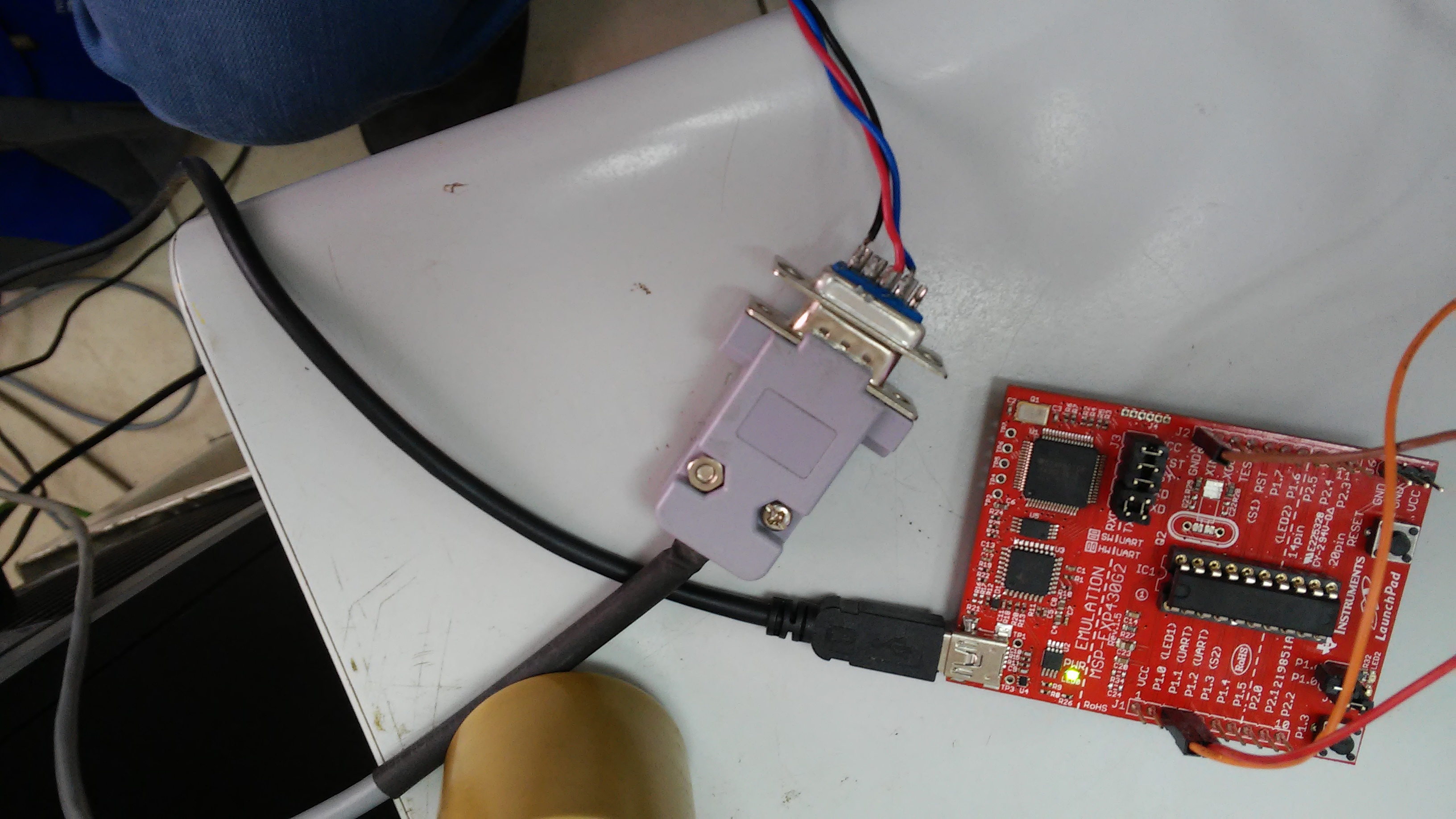
I'm working with msp430g2553 and ccs

i'm sending from the computer to the mcu via rs232 the character a (the software i'm using is com port data emulator)

the USCI0RX interrupt is triggered but the UCA0RXBUF doesn't have the character a

here's the code (i took it from the  code examples):

#include <msp430.h>

unsigned char data;
int main(void)
{
  WDTCTL = WDTPW + WDTHOLD;                 // Stop WDT                               // All P2.x reset
  P1SEL = BIT1 + BIT2 ;                     // P1.1 = RXD, P1.2=TXD
  P1SEL2= BIT1 + BIT2 ;                     // P1.1 = RXD, P1.2=TXD                              // All P3.x reset
  UCA0CTL1 |= UCSSEL_1;                     // CLK = ACLK
  UCA0BR0 = 0x03;                           // 32kHz/9600 = 3.41
  UCA0BR1 = 0x00;                           //
  UCA0MCTL = UCBRS1 + UCBRS0;               // Modulation UCBRSx = 3
  UCA0CTL1 &= ~UCSWRST;                     // **Initialize USCI state machine**
  IE2 |= UCA0RXIE;                          // Enable USCI_A0 RX interrupt

  __bis_SR_register(LPM3_bits + GIE);       // Enter LPM3, interrupts enabled
}

#if defined(__TI_COMPILER_VERSION__) || defined(__IAR_SYSTEMS_ICC__)
#pragma vector=USCIAB0RX_VECTOR
__interrupt void USCI0RX_ISR(void)
#elif defined(__GNUC__)
void __attribute__ ((interrupt(USCIAB0RX_VECTOR))) USCI0RX_ISR (void)
#else
#error Compiler not supported!
#endif
{
  data = UCA0RXBUF;
}

the data doesn't have the character i sent

  • i don't know if the rxifg is set, according to the user guide "UCA0RXIFG Bit 0 USCI_A0 receive interrupt flag. UCA0RXIFG is set when UCA0RXBUF has received a complete character." so when i get the interrupt fired i guess that the UCA0RXIFG is set.
    is there another way to check if the UCA0RXIFG is set?
  • You can just read the RXIFG bit.

    Anyway, it's likely that you're using the wrong baud rate; 32768 ÷ 3 = 10923. Better try the calibrated 1 MHz DCO.
  • do you mean to set
    DCOCTL = CALDCO_1MHZ;
    BCSCTL1 = CALBC1_1MHZ;
    ?
    because adding those lines make the uart not responding to recieve.

    and what do you mean by reading RXIFG (i don't have it)?
  • You have to divide 1 MHz by 104 to get about 9600 baud.

    For the UCA0 module, the RXIFG bit is called UCA0RXIFG.
  • [This doesn't apply if you've already switched to SMCLK, i.e. UCSSEL_2.]

    Do you have a 32kHz crystal installed? Last I saw, the G2 Launchpad came with the crystal Not installed (but it's in the box somewhere.)

    VLOCLK doesn't run at 32kHz. Moreover, in many cases the G2553 ACLK fail-over (if the crystal isn't installed) leads to ACLK behavior that is simply erratic.
  • Thank you for the reply
    i'm sending from the computer the letter 'a'
    when i send it the USCIAB0RX_VECTOR interrupt is fired
    but the UCA0RXBUF is not the letter 'a' (i'm comparing)

    i add the lines:
    DCOCTL = CALDCO_1MHZ;
    BCSCTL1 = CALBC1_1MHZ;
    and change to SMCLK(UCSSEL_2)
    set UCA0BR0 = 0x68(104) for getting baud rate of 9600 (like the COM in the computer)

    how can i get the correct data from UCA0RXBUF?
    i have another question beside that:
    I guess that baud rate can be change dynamically by changing UCA0BR0 , do i need to reset the UART (set UCWRST)?
  • Hi,

    I wanted to show you the new code (the same with minor modifications)

    still UCA0RXBUF is not getting the correct letter

    Furthermore, i notice that both pins (rx and tx) are high. does it make any sense?

    if not, which one need to be low and which one need to be high?

    Thank you

    code:

    #include <msp430.h>
    
    unsigned char data;
    int main(void)
    {
      WDTCTL = WDTPW + WDTHOLD;                 // Stop WDT                               // All P2.x reset
    
      DCOCTL = CALDCO_1MHZ;
      BCSCTL1 = CALBC1_1MHZ;
      P1SEL = BIT1 + BIT2 ;                     // P1.1 = RXD, P1.2=TXD
      P1SEL2= BIT1 + BIT2 ;                     // P1.1 = RXD, P1.2=TXD                              // All P3.x reset
      UCA0CTL1 |= UCSSEL_2;                     // CLK = ACLK
      UCA0BR0 = 0x68;                           // 32kHz/9600 = 3.41
      UCA0BR1 = 0x00;                           //
      UCA0MCTL = UCBRS1 + UCBRS0;               // Modulation UCBRSx = 3
      UCA0CTL1 &= ~UCSWRST;                     // **Initialize USCI state machine**
      IE2 |= UCA0RXIE;                          // Enable USCI_A0 RX interrupt
    
      __bis_SR_register(LPM3_bits + GIE);       // Enter LPM3, interrupts enabled
    }
    
    // Echo back RXed character, confirm TX buffer is ready first
    #if defined(__TI_COMPILER_VERSION__) || defined(__IAR_SYSTEMS_ICC__)
    #pragma vector=USCIAB0RX_VECTOR
    __interrupt void USCI0RX_ISR(void)
    #elif defined(__GNUC__)
    void __attribute__ ((interrupt(USCIAB0RX_VECTOR))) USCI0RX_ISR (void)
    #else
    #error Compiler not supported!
    #endif
    {
      if(UCA0RXBUF == 'a')
    	  IFG2 &= ~UCA0RXIFG;
    
    }
    

  • What character are you getting? Is it always the same? Try a different character: 'U' has a nice bit pattern. Then try 'T' which has a different number of 1-bits.

    What kind of RS-232 converter are you using?

    With these settings (vs the previous ones) you should probably get rid of the "UCA0MCTL = " line. 1000000/9600 is very close (0.1%) to 104.

    Having both pins high is normal. (See e.g. SLAU144J Fig. 15-2.)

    I vaguely recall a note (though I don't see it now) about not changing BR when SWRST=0 , but I also vaguely recall having succeeded on some MSP430 in the past, so I don't think it's explicitly prevented. You may get a glitch on the next character after doing it.
  • Hi, I tried character U and T they both returned the same as a

    but i notice that  i didn't send just a i send a and CR+LF, when i remove CR+LF (send only a) the interrupt didn't work, and if i send the string "ab" the interrupt fired (but still no correct data has been given)

    about the RS-232  converter i'm don't use any converter i have a db9 connector from the pc(COM1) i've attached an image of the circuit

    the cables color from the pc's db9 to the mcu are as follow:

    black -> brown

    red -> orange

    blue -> red

  • If that DB-9 is connected directly to the PC serial port, and then directly to P1.1/P1.2, you shouldn't(!) do that. The levels are probably at least 5V, which can damage your MCU.

    If you find a different way to connect directly to the MCU pins, you should remove the TXD/RXD jumpers from J3 so the USB UART bridge doesn't interfere.

    Is there a reason you're not just using the USB UART bridge on the Launchpad?

  • The levels are 3.5V, maybe i need to reduce it (how can i do it?)
    The jumpers RXD/TXD were horizontal, vertical and remove, and the response stays the same.

    what do you mean by USB UART? is that the usb attched for the power?

    I need in the future to be able to communicate with RS-232 (both transmit and recieve), from slau144j.pdf to do so, i need to use the UART function in pin 1.1 and pin 1.2 (there's no mention of USB UART) nd from the quick start guide the jumpers of TXD/RXD needs to horizontal.
  • 3.5V should be fine (Vcc on the Launchpad is 3.6V). That isn't like the PC serial ports I used to use. (RS-232 is +/- 12V, so even +5V is "cheating".)

    The USB UART is called the "Application" or "back-channel" UART in SLAU318E. Yes, it runs over the "power" USB connection. When you plugged in the USB, Windows should have created you a COMx port with the name "MSP Application UART" (or similar). You can use that COM port with your terminal emulator (9600bps only) . The TXD/RXD jumpers connect that to the P1.1/P1.2 pins.

    If you're connecting directly to the port pins, you should remove the TXD/RXD jumpers from J3, otherwise the programming/bridge chip (TUSBxxx) is also driving those pins. (see also SLAU318E sec 4.3)
  • Thank you for your time.

    So, the problem isn't the code (baud rate 9600 like i need, UCA0MCTL has been removed )
    the TXD/RXD jumpers has been removed.
    the TXD/RXD pins are getting ~3.5V which is not higher than the launchpad's vcc
    the cable are connected correctly

    the software is sending 'a' to COM1 with baud rate 9600 parity none 8 databit and 1 stop bit (n-8-1)
    with one character sending the interrupt not responding with two or more characters the interrupt responding with wrong data (getting 0x00 every time)

    I don't know what i'm missing.
  • I managed to dig up a G2 Launchpad (Rev 1.5) with a G2553 in it.

    Using your code and the Application UART, talking to Win8.1 PuTTY set to 9600-N-1 (no flow control), I get 'a' (or whatever) every time.

    The suggestion is that whatever it is, it is outboard of the Launchpad -- wiring, Host side, or procedure.

    Unfortunately, I can't try those. This is where an oscilloscope comes in handy.
  • How can i set the USB to communicate with the computer (use the virtual COM)?

    my com is COM7 for the msp430 uart application

    the jumpers of TXD/RXD  needs to be removed?

    The wiring of TX/RX pins should be remove also?

    Thank you for your help and time

  • If Device Manager says that your "MSP Application UART" is COM7, then that is what you should give to your terminal emulator. Configure it as though it were an ordinary COM port. (Be sure to turn off "Flow Control" if asked.)

    Since you're running P1.1/P1.2 through the USB (not through your wiring), you should install the J3 TXD/RXD jumpers, and remove your wiring from the pins. The TXD/RXD positions will be rotated (90 degrees) from the others.

    I'm pretty sure that all of this is described in SLAU318E.

**Attention** This is a public forum