This thread has been locked.

If you have a related question, please click the "Ask a related question" button in the top right corner. The newly created question will be automatically linked to this question.

MSP430 I2C slave holding clock line low

Other Parts Discussed in Thread: MSP430F5529

I already asked this on StackOverflow, but actually I think this is surely a much better place to ask.

I'm more of a high level software guy but have been working (experimenting!) on some embedded projects lately so I'm sure there's something obvious I'm missing here, though I have spent over a week trying to debug this and every 'MSP' related link in google is purple at this point...

I currently have an MSP430F5529 set up as an I2C slave device whose only responsibility currently is to receive packets from a master device. The master uses industry grade I2C and has been heavily tested and ruled out as the source of my problem here. I'm using Code composer as my IDE using the TI v15.12.3.LTS compiler. The master has 1k5 pullups on the I2C lines.

What is currently happening is the master queries how many packets (of size 62 bytes) the slave can hold, then sends over a few packets which the MSP is just currently discarding. This is happening every 100ms on the master side and for the minimal example below the MSP will always just send back 63 when asked how many packets it can hold. I have tested the master with a Total Phase Aardvark and everything is working fine with that so I'm sure it's a problem on the MSP side. The problem is as follows:

The program will work for 15-20 minutes, sending over tens of thousands of packets. At some point however the slave starts to hold the clock line low and when paused in debug mode, is shown to be stuck in the start interrupt. The same sequence of events is happening every single time to cause this.

1) Master queries how many packets the MSP can hold.
2) A packet is sent successfully
3) Another packet is attempted but < 62 bytes are received by the MSP (counted by logging how many Rx interrupts I receive). No stop condition is sent so master times out.
4) Another packet is attempted. A single byte is sent before the stop condition is sent.
5) Another packet is attempted to be sent. A start interrupt, then a Tx interrupt happens and the device hangs.

Ignoring the fact that I'm not handling the timeout errors on the master side, something very strange is happening to cause that sequence of events, but that's what happens every single time.


Below is the minimal working example which is reproducing the problem. My particular concern is with the SetUpRx and SetUpTx functions. The examples that the Code Composer Resource Explorer gives only has examples of Rx or Tx, I'm not sure if I'm combining them in the right way. I also tried removing the SetUpRx completely, putting the device into transmit mode and replacing all calls to SetUpTx/Rx with mode = TX_MODE/RX_MODE, which did work but still eventually holds the clock line low. Ultimately I'm not 100% sure on how to set this up to receive both Rx and Tx requests.

#include "driverlib.h"

#define SLAVE_ADDRESS 			(0x48)

// During main loop, set mode to either RX_MODE or TX_MODE
// When I2C is finished, OR mode with I2C_DONE, hence upon exit mdoe will be one of I2C_RX_DONE or I2C_TX_DONE
#define RX_MODE					(0x01)
#define TX_MODE					(0x02)
#define I2C_DONE				(0x04)
#define I2C_RX_DONE				(RX_MODE | I2C_DONE)
#define I2C_TX_DONE				(TX_MODE | I2C_DONE)


/**
 * I2C message ids
 */
#define MESSAGE_ADD_PACKET		(3)
#define MESSAGE_GET_NUM_SLOTS	        (5)

static volatile uint8_t mode = RX_MODE;		// current mode, TX or RX

static volatile uint8_t rx_buff[64] = {0};	// where rx data is written
static volatile uint8_t* rx_data = rx_buff;	// pointer to next rx byte write location

static volatile uint8_t tx_len = 0;		// number of bytes to reply with

static inline void SetUpRx(void) {
	// Specify receive mode
	USCI_B_I2C_setMode(USCI_B0_BASE, USCI_B_I2C_RECEIVE_MODE);

	// Enable I2C Module to start operations
	USCI_B_I2C_enable(USCI_B0_BASE);

	// Enable interrupts
	USCI_B_I2C_clearInterrupt(USCI_B0_BASE, USCI_B_I2C_TRANSMIT_INTERRUPT);
	USCI_B_I2C_enableInterrupt(USCI_B0_BASE, USCI_B_I2C_START_INTERRUPT + USCI_B_I2C_RECEIVE_INTERRUPT + USCI_B_I2C_STOP_INTERRUPT);

	mode = RX_MODE;
}


static inline void SetUpTx(void) {
	//Set in transmit mode
	USCI_B_I2C_setMode(USCI_B0_BASE, USCI_B_I2C_TRANSMIT_MODE);

	//Enable I2C Module to start operations
	USCI_B_I2C_enable(USCI_B0_BASE);

	//Enable master trasmit interrupt
	USCI_B_I2C_clearInterrupt(USCI_B0_BASE, USCI_B_I2C_RECEIVE_INTERRUPT);
	USCI_B_I2C_enableInterrupt(USCI_B0_BASE, USCI_B_I2C_START_INTERRUPT + USCI_B_I2C_TRANSMIT_INTERRUPT + USCI_B_I2C_STOP_INTERRUPT);

	mode = TX_MODE;
}


/**
 * Parse the incoming message and set up the tx_data pointer and tx_len for I2C reply
 *
 * In most cases, tx_buff is filled with data as the replies that require it either aren't used frequently or use few bytes.
 * Straight pointer assignment is likely better but that means everything will have to be volatile which seems overkill for this
 */
static void DecodeRx(void) {
	static uint8_t message_id = 0;

	message_id = (*rx_buff);
	rx_data = rx_buff;

	switch (message_id) {
	case MESSAGE_ADD_PACKET:		// Add some data...
		// do nothing for now
		tx_len = 0;

		break;

	case MESSAGE_GET_NUM_SLOTS:		// How many packets can we send to device
		tx_len = 1;

		break;

	default:
		tx_len = 0;

		break;
	}
}

void main(void) {
    //Stop WDT
    WDT_A_hold(WDT_A_BASE);

    //Assign I2C pins to USCI_B0
    GPIO_setAsPeripheralModuleFunctionInputPin(GPIO_PORT_P3, GPIO_PIN0 + GPIO_PIN1);

    //Initialize I2C as a slave device
    USCI_B_I2C_initSlave(USCI_B0_BASE, SLAVE_ADDRESS);

    // go into listening mode
    SetUpRx();

    while(1) {
    	__bis_SR_register(LPM4_bits + GIE);

    	// Message received over I2C, check if we have anything to transmit
    	switch (mode) {
    	case I2C_RX_DONE:
    	DecodeRx();
	if (tx_len > 0) {
		// start a reply
		SetUpTx();
	} else {
		// nothing to do, back to listening
		mode = RX_MODE;
	}
	break;

    	case I2C_TX_DONE:
    		// go back to listening
    		SetUpRx();

    		break;

	default:
		break;
    	}
    }
}

/**
 * I2C interrupt routine
 */
#pragma vector=USCI_B0_VECTOR
__interrupt void USCI_B0_ISR(void) {
    switch(__even_in_range(UCB0IV,12)) {
    case USCI_I2C_UCSTTIFG:
    	break;

    case USCI_I2C_UCRXIFG:
    	*rx_data = USCI_B_I2C_slaveGetData(USCI_B0_BASE);
    	++rx_data;

        break;

    case USCI_I2C_UCTXIFG:
    	if (tx_len > 0) {
		USCI_B_I2C_slavePutData(USCI_B0_BASE, 63);
		--tx_len;
    	}

	break;

    case USCI_I2C_UCSTPIFG:
    	// OR'ing mode will let it be flagged in the main loop
        mode |= I2C_DONE;
        __bic_SR_register_on_exit(LPM4_bits);

        break;
    }
}

Any help on this would be much appreciated and if you need any more information please ask.
Thank you!

  • Hi Brian,

    Thank you for the detailed description, I have a few recommendations:

    1. Larger pull-up values (4.7 or 10 kOhm), reduce the I2C clock to 100 kHz if not used already.
    2. Clear both transmit and receive interrupt flags in SetUpRx/Tx, and disable the interrupt you are not currently using.
    3. Do not initialize the start interrupt if you are not using it in your ISR, you don't have to re-enable the stop interrupt each time.
    4. Shorten DecodeRx and run through SetUpTx as quickly as possible (either disable/re-enable the USCI module in each or don't bother re-enabling it every time).
    5. Try increasing your DCO/MCLK frequency to lower instruction time.

    The fact that the code works so long before breaking leads me to believe that there is a race condition involved that is trapping the USCI in an unknown state, you will need to debug the system further before we can know for sure.

    Regards,
    Ryan
  • Hi Ryan,

    Thanks for the response. In regards to your recommendations.

    1. I'm already on 100kHz but will soldier on some 10k's to another board to test.

    3. The start interrupt was enabled due to debugging, but I'll remove it

    4. In regards to this, on the master side, it is waiting 2ms between the write and read, so I don't think the length of these functions should be a problem as the MSP has 2ms to process an incoming message. (note also it waits 2ms between sending packets, essentially 2ms between any two I2C commands).

    5. I added this to main to (I think!) initialise the MCLK frequency to 8Mhz, correct me if this is wrong though.

    #define UCS_MCLK_DESIRED_FREQUENCY_IN_KHZ  (8000)
    #define UCS_MCLK_FLLREF_RATIO              (244)
    
    ...
    
    
    PMM_setVCore(PMM_CORE_LEVEL_1);
    
    // if XT2 Crystal fails to turn on, use DCO for clock generation
    // Set DCO FLL reference = REFO
    UCS_initClockSignal(UCS_FLLREF, UCS_REFOCLK_SELECT, UCS_CLOCK_DIVIDER_1);
    
    // Set Ratio and Desired MCLK Frequency  and initialize DCO
    // this will also provide delay to settle the DCO CLOCK
    UCS_initFLLSettle(UCS_MCLK_DESIRED_FREQUENCY_IN_KHZ, UCS_MCLK_FLLREF_RATIO);
    
    UCS_initClockSignal(UCS_ACLK, UCS_DCOCLK_SELECT, UCS_CLOCK_DIVIDER_1);
    
    //Set ACLK = REFO
    UCS_initClockSignal(UCS_MCLK, UCS_DCOCLK_SELECT, UCS_CLOCK_DIVIDER_1);


    This was supplied by a colleague who's a bit more familiar with MSP coding but isn't able to solve my I2C issue.


    For point 2, I'm still not sure what exactly the correct method is for setting up a slave to handle Tx/Rx. I removed the SetUpTx/SetUpRx and replaced it with the following and the code still works as before (with hanging, though it happens quicker this time, ~2-3 mins as opposed to 15-20 mins). I'm not sure why both setups work, I would expect only one to, however perhaps both are actually slightly wrong. Are you able to advise on what the correct method is for setting up a slave to handle Rx/Tx with a message/command id method as I am doing (i.e. decoding the incoming data and replying with whatever)


    void main(void) { //Stop WDT WDT_A_hold(WDT_A_BASE); ... USCI_B_I2C_setMode(USCI_B0_BASE, USCI_B_I2C_TRANSMIT_MODE); //Enable I2C Module to start operations USCI_B_I2C_enable(USCI_B0_BASE); USCI_B_I2C_enableInterrupt(USCI_B0_BASE, USCI_B_I2C_RECEIVE_INTERRUPT + USCI_B_I2C_STOP_INTERRUPT); mode = RX_MODE; while(1) { __bis_SR_register(LPM4_bits + GIE); // Message received over I2C, check if we have anything to transmit switch (mode) { case I2C_RX_DONE: DecodeRx(); if (tx_len > 0) { // start a reply mode = TX_MODE; } else { // nothing to do, back to listening mode = RX_MODE; } break; case I2C_TX_DONE: mode = RX_MODE; break; default: break; } } }

    Thanks

  • I don't know why you are also messing with ACLK, but otherwise the MCLK initialization appears fine.

    I just noticed a big issue with your slave's attempt to transmit the single byte of data. I doubt the USCI_I2C_UCTXIFG case is ever entered since this flag is only set when UCTXBUF is populated by using USCI_B_I2C_slavePutData, whose only occurence is inside the UCTXIFG handler. What you should do instead is use the USCI_I2C_UCSTTIFG, determine if you are in TX_MODE, and perform the USCI_B_I2C_slavePutData & --txlen commands. You don't need USCI_I2C_UCTXIFG since you only expect to send one byte at any given time.

    You would benefit from having oscilloscope or logic analyzer screenshots to visualize your communication sequences.

    Regards,
    Ryan
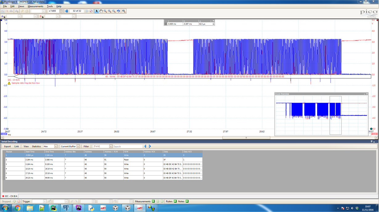
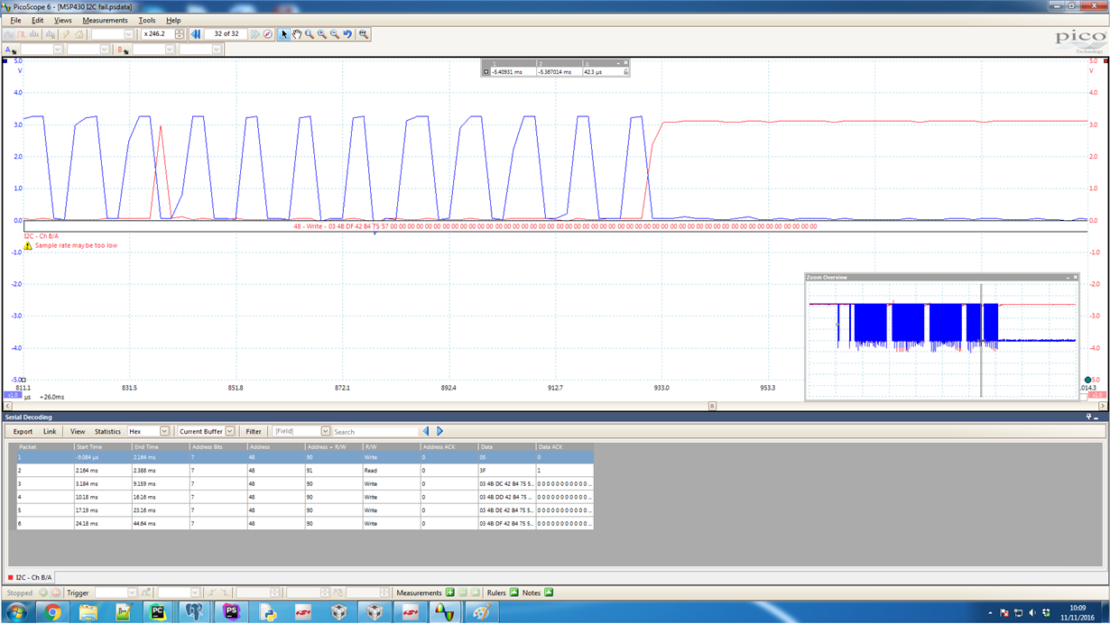
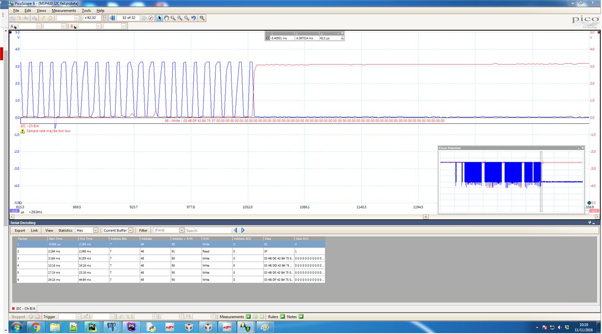
  • Currently I have a Picoscope set up so I've attached three images of an example of the packet before the msp hangs during an example run of my program. First pic is the full 62 byte packet (0's are expected since the data coming from the master is just dummy data). The gap in the middle I'm not sure if it's an artifact of the picoscope or whether it's something real that's happening. In any case the second image is a zoom of that and the final image is a zoom of the end of the packet, where the clock goes low and stays low.

    In regards to your point about the Tx interrupt. I can confirm that the Tx interrupt is entered as I did a bit of logging on the MSP and it was always entered twice before the stop interrupt was called. I used the code from the examples in the Code Composer Resource Explorer, which in both the single Tx and multiple Tx case wait for the TX interrupt before calling slavePutData.

    Interestingly enough, I also tried running this using the usci_b_i2c_ex1_slaveRxMultiple example from the resource explorer, with an addition of the 8Mhz clock setup and the buffer size changed to 64 bytes, and the same thing happens. The last packet has that gap midway then eventually holds the clk line down. When the debugger is suspended, it's shown to the in the stop interrupt on the __bic_SR_register_on_exit(LPM0_bits) command. I was advised on StackOverflow to investigate whether this was erratum USCI30 or USCI39 which I still have to look at. Today I'll also have a chance to solder on some higher pullups to give that a try. 

    I'm also starting to wonder about the master i2c side. I can't imagine that's at fault here since it's been used for a long time on many projects and this issue hasn't been seen before, however you never know.

    Thanks for your help so far.

    Regards,

    Brian.

  • My mistake on the UCTXIFG state, I had forgotten that it is set when ready to transmit new data. You can disregard my previous post.

    Since communication is valid for several minutes it is definitely worth investigating some of the I2C-related errata. USCI30 is doubtful as the UCBxRXIFG is serviced very quickly and efficiently, but perhaps the wake-up time from LPM4 is involved? You mention LPM0 in the latest post, maybe you should try this low-power mode to see if anything changes.

    USCI39 could possibly be an issue since the GIE is reset and set each time an ISR is entered and exited, respectively. But this would assume that UCSTTIFG, UCSTPIFG, or UCNACKIFG are set while you are servicing the ISR, you could check the status of these flags during interrupt operation to be sure or try the suggested workaround.

    If the last bit of the last screenshot is a slave ACK then it would appear that the MSP430 is still operating properly, in which case there may be some confusion between the master and slave as to who should be sending or receiving data. If you can detect this state on the master end then you should be able to compensate by at least re-starting the I2C lines and re-sending the packet, not ideal but a possible workaround.

    Regards,
    Ryan
  • Hi Ryan,

    So actually I think I have solved this. My master is using FreeRTOS and it turns out that a higher priority task was (unexpectedly) interrupting the I2C at certain, infrequent, intervals and causing it to timeout. The I2C driver should be able to handle clock stretching but these delays were taking a while due to some complex background tasks that were occurring.
    The reason I did not initially suspect the master was that I hadn't seen this clk line holding before, but my other projects have a data rate much much lower than this project, so perhaps the failure rate is on the order of days/weeks (and might explain some of the unexpected issues I have infrequently had on other projects). Seems I have a lot to look at on the master though to properly solve this, but I've implemented a quick workaround for now.

    Thanks very much for your help on what must have felt like an unsolvable problem!

    Regards,
    Brian

**Attention** This is a public forum