This thread has been locked.

If you have a related question, please click the "Ask a related question" button in the top right corner. The newly created question will be automatically linked to this question.

MSP432 UART receive multiple Byte

Other Parts Discussed in Thread: CC3200

Hi Everyone.

I am currently trying to use the backdoor UART to receive multiple bytes from PC Host.

I used the example code "uart_pc_echo_12mhz_brclk" and tested the code with Coolterm.

My bytes("abcd") is sent from Coolterm. I was succssfully interruped.

When I check the value of "UCA0RXBUF".I saw the "a" there,

then i continue the excution and get interrupted again.However, instead of seeing "b". I am seeing "d" in UCA0RXBUF.

Somehow my middle bytes are missing. 

I appoligize if the this is very simple question.

Did i parse my bytes incorrectly? if so. How do i extract all of my bytes from UCA0RXBUF? 

Thank you,

Eddy

/*
 * -------------------------------------------
 *    MSP432 DriverLib - v3_21_00_05
 * -------------------------------------------
 *
 * --COPYRIGHT--,BSD,BSD
 * Copyright (c) 2016, Texas Instruments Incorporated
 * All rights reserved.
 *
 * Redistribution and use in source and binary forms, with or without
 * modification, are permitted provided that the following conditions
 * are met:
 *
 * *  Redistributions of source code must retain the above copyright
 *    notice, this list of conditions and the following disclaimer.
 *
 * *  Redistributions in binary form must reproduce the above copyright
 *    notice, this list of conditions and the following disclaimer in the
 *    documentation and/or other materials provided with the distribution.
 *
 * *  Neither the name of Texas Instruments Incorporated nor the names of
 *    its contributors may be used to endorse or promote products derived
 *    from this software without specific prior written permission.
 *
 * THIS SOFTWARE IS PROVIDED BY THE COPYRIGHT HOLDERS AND CONTRIBUTORS "AS IS"
 * AND ANY EXPRESS OR IMPLIED WARRANTIES, INCLUDING, BUT NOT LIMITED TO,
 * THE IMPLIED WARRANTIES OF MERCHANTABILITY AND FITNESS FOR A PARTICULAR
 * PURPOSE ARE DISCLAIMED. IN NO EVENT SHALL THE COPYRIGHT OWNER OR
 * CONTRIBUTORS BE LIABLE FOR ANY DIRECT, INDIRECT, INCIDENTAL, SPECIAL,
 * EXEMPLARY, OR CONSEQUENTIAL DAMAGES (INCLUDING, BUT NOT LIMITED TO,
 * PROCUREMENT OF SUBSTITUTE GOODS OR SERVICES; LOSS OF USE, DATA, OR PROFITS;
 * OR BUSINESS INTERRUPTION) HOWEVER CAUSED AND ON ANY THEORY OF LIABILITY,
 * WHETHER IN CONTRACT, STRICT LIABILITY, OR TORT (INCLUDING NEGLIGENCE OR
 * OTHERWISE) ARISING IN ANY WAY OUT OF THE USE OF THIS SOFTWARE,
 * EVEN IF ADVISED OF THE POSSIBILITY OF SUCH DAMAGE.
 * --/COPYRIGHT--*/
/******************************************************************************
 * MSP432 UART - PC Echo with 12MHz BRCLK
 *
 * Description: This demo echoes back characters received via a PC serial port.
 * SMCLK/DCO is used as a clock source and the device is put in LPM0
 * The auto-clock enable feature is used by the eUSCI and SMCLK is turned off
 * when the UART is idle and turned on when a receive edge is detected.
 * Note that level shifter hardware is needed to shift between RS232 and MSP
 * voltage levels.
 *
 *               MSP432P401
 *             -----------------
 *            |                 |
 *            |                 |
 *            |                 |
 *       RST -|     P1.3/UCA0TXD|----> PC (echo)
 *            |                 |
 *            |                 |
 *            |     P1.2/UCA0RXD|<---- PC
 *            |                 |
 *
 * Author: Timothy Logan
*******************************************************************************/
/* DriverLib Includes */
#include "driverlib.h"

/* Standard Includes */
#include <stdint.h>
//#include "printf.h"
#include <stdbool.h>
#include "msp.h"
#include <driverlib.h>
#include <HAL_I2C.h>
#include <HAL_OPT3001.h>
#include <stdio.h>
#include <stdint.h>
#include <string.h>
//#include <uart_driver.h>

/* UART Configuration Parameter. These are the configuration parameters to
 * make the eUSCI A UART module to operate with a 9600 baud rate. These
 * values were calculated using the online calculator that TI provides
 * at:
 *software-dl.ti.com/.../index.html
 */


const eUSCI_UART_Config uartConfig =
{
        EUSCI_A_UART_CLOCKSOURCE_SMCLK,          // SMCLK Clock Source
        78,                                     // BRDIV = 78
        2,                                       // UCxBRF = 2
        0,                                       // UCxBRS = 0
        EUSCI_A_UART_NO_PARITY,                  // No Parity
        EUSCI_A_UART_LSB_FIRST,                  // LSB First
        EUSCI_A_UART_ONE_STOP_BIT,               // One stop bit
        EUSCI_A_UART_MODE,                       // UART mode
        EUSCI_A_UART_OVERSAMPLING_BAUDRATE_GENERATION  // Oversampling
};

/* Graphic library context */


//Receive UART Variables
#define NUM_RX_CHARS 64
char rxMsgData[NUM_RX_CHARS] = "";
int numMsgsRx = 0;
int tempIndex = 5;
int numChars = 0;
#define MAX_STR_LENGTH 271

#define FALSE 0
#define TRUE  1

typedef struct{
	unsigned char newStringReceived;
	char          txString[MAX_STR_LENGTH];
	char          rxString[MAX_STR_LENGTH];
}s_test;

extern s_test test;
s_test test = {
	FALSE,
	"",
	""
};
/* Variable for storing lux value returned from OPT3001 */
float lux;

/* Timer_A Up Configuration Parameter */
const Timer_A_UpModeConfig upConfig =
{
        TIMER_A_CLOCKSOURCE_ACLK,               // ACLK Clock SOurce
        TIMER_A_CLOCKSOURCE_DIVIDER_1,          // ACLK/1 = 3MHz
        200,                                    // 200 tick period
        TIMER_A_TAIE_INTERRUPT_DISABLE,         // Disable Timer interrupt
        TIMER_A_CCIE_CCR0_INTERRUPT_DISABLE,    // Disable CCR0 interrupt
        TIMER_A_DO_CLEAR                        // Clear value
};

/* Timer_A Compare Configuration Parameter  (PWM) */
Timer_A_CompareModeConfig compareConfig_PWM =
{
        TIMER_A_CAPTURECOMPARE_REGISTER_3,          // Use CCR3
        TIMER_A_CAPTURECOMPARE_INTERRUPT_DISABLE,   // Disable CCR interrupt
        TIMER_A_OUTPUTMODE_TOGGLE_SET,              // Toggle output but
        100                                         // 50% Duty Cycle
};


int main(void)
{
    /* Halting WDT  */
    MAP_WDT_A_holdTimer();
    /* Set the core voltage level to VCORE1 */
    MAP_PCM_setCoreVoltageLevel(PCM_VCORE1);

    /* Set 2 flash wait states for Flash bank 0 and 1*/
    MAP_FlashCtl_setWaitState(FLASH_BANK0, 2);
    MAP_FlashCtl_setWaitState(FLASH_BANK1, 2);

    // the UART DOES NOT WORK FOR more than 24Mhz
    MAP_CS_setDCOCenteredFrequency(CS_DCO_FREQUENCY_24);
    MAP_CS_initClockSignal(CS_MCLK, CS_DCOCLK_SELECT, CS_CLOCK_DIVIDER_2 );
    MAP_CS_initClockSignal(CS_HSMCLK, CS_DCOCLK_SELECT, CS_CLOCK_DIVIDER_2 );
    MAP_CS_initClockSignal(CS_SMCLK, CS_DCOCLK_SELECT, CS_CLOCK_DIVIDER_2 );
    MAP_CS_initClockSignal(CS_ACLK, CS_REFOCLK_SELECT, CS_CLOCK_DIVIDER_2);


    Init_I2C_GPIO();
    I2C_init();


    /* Selecting P1.2 and P1.3 in UART mode */
    MAP_GPIO_setAsPeripheralModuleFunctionInputPin(GPIO_PORT_P1,
            GPIO_PIN1 | GPIO_PIN2 | GPIO_PIN3, GPIO_PRIMARY_MODULE_FUNCTION);

    /* Setting DCO to 12MHz */

    /* Configuring UART Module */
    MAP_UART_initModule(EUSCI_A0_BASE, &uartConfig);

    /* Enable UART module */
    MAP_UART_enableModule(EUSCI_A0_BASE);

    /* Enabling UART interrupts */
    MAP_UART_enableInterrupt(EUSCI_A0_BASE, EUSCI_A_UART_RECEIVE_INTERRUPT);
    MAP_Interrupt_enableInterrupt(INT_EUSCIA0);
    MAP_Interrupt_enableSleepOnIsrExit();
    MAP_Interrupt_enableMaster();

    //sample test code for i2c, this code is not interrupt based.
    //I2C_write8(0x39,0x80, 0x03);
    //I2C_write8(0x39,0x81, 0x01);

    //int16_t raw;
    //int16_t raw_2;
    //raw = I2C_read8(0x39,0x60);
    //raw_2 = I2C_read16(0x80);
    //I2C_write8(0x39,0x80, 0x03);
    //I2C_write8(0x39,0x81, 0x01);
    //raw = I2C_read8(0x39,0x60);
    //raw_2 = I2C_read16(0x80);


    char *s = "printf test";
    char c = '!';
    int i = -12345;
    unsigned u = 4321;
    long int l = -123456780;
    long unsigned n = 1098765432;
    unsigned x = 0xABCD;
           %x\r\n", x);

    while(1)
    {
        MAP_PCM_gotoLPM0();
    }
}

/* EUSCI A0 UART ISR - Echoes data back to PC host */
/* This code works the following way
 * 1) Open a cool term serial port
 * 2) the board has backdoor uart and will shows up as comm port
 * 3)connect to that port in coolterm
 * 4)send some strings
 * 5)add a break point at below interrupt.
 * 6)the byte send should be stored in the "receiveByte" address
 * 7)Then the byte will be eched back to the cool term
 */

void EUSCIA0_IRQHandler(void)
{
    uint32_t status = MAP_UART_getEnabledInterruptStatus(EUSCI_A0_BASE);
    char receiveByte = UCA0RXBUF;  //This is the address where the received byte is stored

    MAP_UART_clearInterruptFlag(EUSCI_A0_BASE, status);


    if(status & EUSCI_A_UART_RECEIVE_INTERRUPT_FLAG)
    {

        MAP_UART_transmitData(EUSCI_A0_BASE, receiveByte);
    }

}

  • MSP432 does have one byte eUSCI RX hardware buffer. If such conditions do not meet your requirements I recommend to look at CC3200.
  • With such a setup (one byte receive buffer), you cannot single-step trough real-time communication. That should be self-explanatory...

  • eUSCI interchangeable baud rates for unsynced (without synchronization feedback) connections in all cases lower that working clocks for MCU data buses and CPU. The hardware receive buffer is (should be) decoupled from receive shift register (binary deserializer), so there is enough headroom (in ticks) to get data from hardware buffer. If data block length of receiving data is not predetermined and synced, it is unclear when to send interrupt signal to a CPU or DMA to get such data away to a software buffer or additional processing on-a-go.

  • Hi Alexey, if i know that i will be sending say predetermined bytes each time(5 bytes). How do i set up my code to receive those 5 bytes? Thansk, Eddy
  • As we mentioned earlier, for MS432 this byte length is always 8bits-1byte. So you need: if you are using CPU, configure EUSCIA0_IRQHandler() interrupt routine in such a way, that every new byte will be added to a global RAM-buffer-string line until end-line character will be received. Then you can process your received string (or data) further. It actually works without any problem if your UART channel speed vs. noise is in good ratio.

  • For 5 bytes - process data array after receiving 5 bytes. But you need to determine the delays between every such block of data, otherwise in case loosing 1 byte in a noisy channel all new data will be shifted by 1 byte. And it is not a good practice to do that without flow control.

  • I agree with f.m. that 1-byte eUSCI setup is not the best (or most efficient) for a single data bus architecture, but may be TI made it simpler because MSP are "extremely-low-power". If you compare with TI's DSPs: up to 6x 256-bit data-buses!, multichannel DMAs with 1-cycle execution concurrently, dedicated command buses, main data bases, axillary data buses, multichannel RAM access and so on.
    I don't think that TI didn't think ten times before make it as it is.

  • Hi Alexey,

    Sorry to trouble you for another question.

    Here is my updated code per your suggestion.

    As you suggested, Now upon the arraive of first byte and i store them into a array until a "\n" is received.

    The codes expected to work like this

    1)Received the first array of bytes and store them into the buffer 

    2)Set test.newStringReceived to true, so if blocks the upcomming arrays until it is cleared(false)

    3)The loop in the main function will constantly check the test.newStringReceived, if it is true, it will copy the data from buffer and clear it.

    4)The code will be able to receive the next array of bytes

    The 1) and 2) works well, However, The 3) part never get triggered.

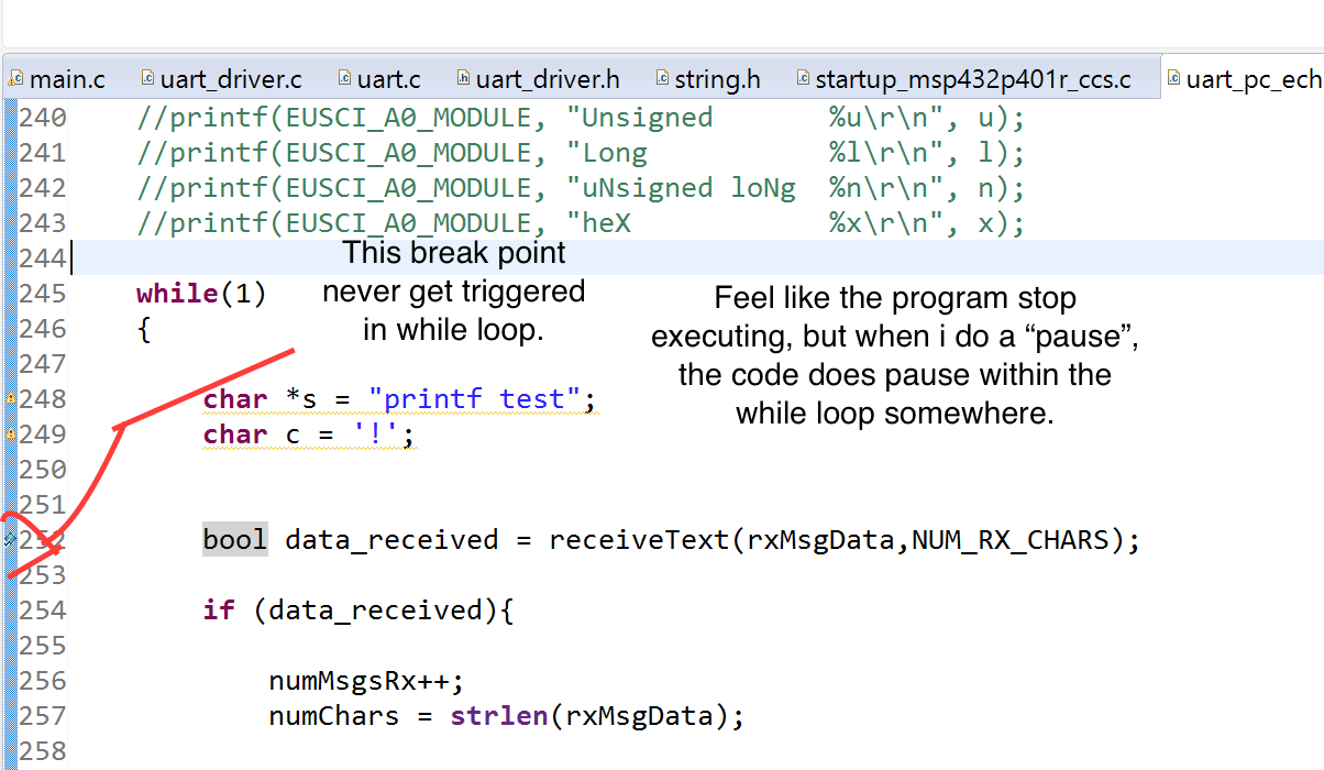
    This is the strange part. if i do a "pause", in CCS. And I step into the code. The 3) will get excuated.(It clears the  test.newStringReceived as the logic expected). However, If i just leave it running hope the the program will automaticly clear the  test.newStringReceived upon the arrival of the data, it will neven happen.

    It seems like the while loop stopped excuating, (Even i put a break point inside of while loop. It does not get tiggered).

    (This happends after 1) and 2),(after a interrupt?), this does not happends if the interrupt neven get triggered)

    There seems to be some intengible thing happening and I am so frustrated by this.

    I would really appricate some insights.

    Thanks,

    Eddy

    #include "driverlib.h"
    
    /* Standard Includes */
    #include <stdint.h>
    //#include "printf.h"
    #include <stdbool.h>
    #include "msp.h"
    #include <driverlib.h>
    #include <HAL_I2C.h>
    #include <HAL_OPT3001.h>
    #include <stdio.h>
    #include <stdint.h>
    #include <string.h>
    //#include <uart_driver.h>
    
    /* UART Configuration Parameter. These are the configuration parameters to
     * make the eUSCI A UART module to operate with a 9600 baud rate. These
     * values were calculated using the online calculator that TI provides
     * at:
     *software-dl.ti.com/.../index.html
     */
    
    
    const eUSCI_UART_Config uartConfig =
    {
            EUSCI_A_UART_CLOCKSOURCE_SMCLK,          // SMCLK Clock Source
            78,                                     // BRDIV = 78
            2,                                       // UCxBRF = 2
            0,                                       // UCxBRS = 0
            EUSCI_A_UART_NO_PARITY,                  // No Parity
            EUSCI_A_UART_LSB_FIRST,                  // LSB First
            EUSCI_A_UART_ONE_STOP_BIT,               // One stop bit
            EUSCI_A_UART_MODE,                       // UART mode
            EUSCI_A_UART_OVERSAMPLING_BAUDRATE_GENERATION  // Oversampling
    };
    
    /* Graphic library context */
    
    
    //Receive UART Variables
    #define NUM_RX_CHARS 64
    char rxMsgData[NUM_RX_CHARS] = "";
    int numMsgsRx = 0;
    int tempIndex = 5;
    int numChars = 0;
    
    #define MAX_STR_LENGTH 271
    uint8_t rx_buffer[1024];
    uint16_t bufferIndex = 0;
    
    
    #define FALSE 0
    #define TRUE  1
    
    typedef struct{
    	unsigned char newStringReceived;
    	char          txString[MAX_STR_LENGTH];
    	char          rxString[MAX_STR_LENGTH];
    }s_test;
    
    extern s_test test;
    s_test test = {
    	FALSE,
    	"",
    	""
    };
    /* Variable for storing lux value returned from OPT3001 */
    float lux;
    
    /* Timer_A Up Configuration Parameter */
    const Timer_A_UpModeConfig upConfig =
    {
            TIMER_A_CLOCKSOURCE_ACLK,               // ACLK Clock SOurce
            TIMER_A_CLOCKSOURCE_DIVIDER_1,          // ACLK/1 = 3MHz
            200,                                    // 200 tick period
            TIMER_A_TAIE_INTERRUPT_DISABLE,         // Disable Timer interrupt
            TIMER_A_CCIE_CCR0_INTERRUPT_DISABLE,    // Disable CCR0 interrupt
            TIMER_A_DO_CLEAR                        // Clear value
    };
    
    /* Timer_A Compare Configuration Parameter  (PWM) */
    Timer_A_CompareModeConfig compareConfig_PWM =
    {
            TIMER_A_CAPTURECOMPARE_REGISTER_3,          // Use CCR3
            TIMER_A_CAPTURECOMPARE_INTERRUPT_DISABLE,   // Disable CCR interrupt
            TIMER_A_OUTPUTMODE_TOGGLE_SET,              // Toggle output but
            100                                         // 50% Duty Cycle
    };
    
    
    bool receiveText(char* data, int maxNumChars){
    	bool result = false;
        if(test.newStringReceived == TRUE){
        	result = true;
        	strncpy(data,test.rxString,maxNumChars);
        	test.newStringReceived = FALSE;
        }
        return result;
    }


    int main(void)
    {
        /* Halting WDT  */
        MAP_WDT_A_holdTimer();
        /* Set the core voltage level to VCORE1 */
        MAP_PCM_setCoreVoltageLevel(PCM_VCORE1);
    
        /* Set 2 flash wait states for Flash bank 0 and 1*/
        MAP_FlashCtl_setWaitState(FLASH_BANK0, 2);
        MAP_FlashCtl_setWaitState(FLASH_BANK1, 2);
    
        // the UART DOES NOT WORK FOR more than 24Mhz
        MAP_CS_setDCOCenteredFrequency(CS_DCO_FREQUENCY_24);
        MAP_CS_initClockSignal(CS_MCLK, CS_DCOCLK_SELECT, CS_CLOCK_DIVIDER_2 );
        MAP_CS_initClockSignal(CS_HSMCLK, CS_DCOCLK_SELECT, CS_CLOCK_DIVIDER_2 );
        MAP_CS_initClockSignal(CS_SMCLK, CS_DCOCLK_SELECT, CS_CLOCK_DIVIDER_2 );
        MAP_CS_initClockSignal(CS_ACLK, CS_REFOCLK_SELECT, CS_CLOCK_DIVIDER_2);
    
    
        Init_I2C_GPIO();
        I2C_init();


        /* Selecting P1.2 and P1.3 in UART mode */
        MAP_GPIO_setAsPeripheralModuleFunctionInputPin(GPIO_PORT_P1,
                GPIO_PIN1 | GPIO_PIN2 | GPIO_PIN3, GPIO_PRIMARY_MODULE_FUNCTION);
    
        /* Setting DCO to 12MHz */
    
        /* Configuring UART Module */
        MAP_UART_initModule(EUSCI_A0_BASE, &uartConfig);
    
        /* Enable UART module */
        MAP_UART_enableModule(EUSCI_A0_BASE);
    
        /* Enabling UART interrupts */
        MAP_UART_enableInterrupt(EUSCI_A0_BASE, EUSCI_A_UART_RECEIVE_INTERRUPT);
        MAP_Interrupt_enableInterrupt(INT_EUSCIA0);
        MAP_Interrupt_enableSleepOnIsrExit();
        MAP_Interrupt_enableMaster();
    
        while(1)
        {
    
            char *s = "printf test";
            char c = '!';
    
            //The receiveText will check continuously whether the data is received , by checking the test.newStringReceived.
            //receiveText also clear the test.newStringReceived to FALSE, so the next array of bytes can be received.
            bool data_received = receiveText(rxMsgData,NUM_RX_CHARS);
    
    
        	if (data_received){
    
        		numMsgsRx++;
        		numChars = strlen(rxMsgData);
    
    
        	}


    		// Configure WDT
    		// For LPM3 Clock Source should be BCLK or VLOCLK
    
    
    		// Start WDT
    
    		//Go to LPM0 (Cannot use LPM3 because we won't accurately receive UART data)
    		//MAP_PCM_gotoLPM0();
        }
    }
    
    /* EUSCI A0 UART ISR - Echoes data back to PC host */
    /* This code works the following way
     * 1) Open a cool term serial port
     * 2) the board has backdoor uart and will shows up as comm port
     * 3)connect to that port in coolterm
     * 4)send some strings
     * 5)add a break point at below interrupt.
     * 6)the byte send should be stored in the "receiveByte" address
     * 7)Then the byte will be eched back to the cool term
     */
    
    void uartReceive(char data){
    	static char rxInProgress = FALSE;
    	static char pieceOfString[MAX_STR_LENGTH] = "";           // Holds the new addition to the string
    	static char charCnt = 0;
    
    	if( !rxInProgress){
    		if ((data != '\n') ){
    			pieceOfString[0] = '\0';
    			rxInProgress = TRUE;
    			pieceOfString[0] = data;
    			charCnt = 1;
    		}
    	}else{ // in progress
    		if((data == '\n')){
    			rxInProgress = FALSE;
    			if (test.newStringReceived == FALSE){ // don't mess with the string while main processes it.
    				pieceOfString[charCnt]='\0';
    				__no_operation();
    				charCnt++;
    				strncpy(test.rxString,pieceOfString,charCnt);
    				__no_operation();
    				test.newStringReceived = TRUE;
    				__no_operation();
    			}
    		}else{
    			if (charCnt >= MAX_STR_LENGTH){
    				rxInProgress = FALSE;
    			}else{
    				pieceOfString[charCnt++] = data;
    				//charCnt++;
    			}
    		}
    	}
    }
    
    void EUSCIA0_IRQHandler(void)
    {
        uint32_t status = MAP_UART_getEnabledInterruptStatus(EUSCI_A0_BASE);
        //char receiveByte = UCA0RXBUF;  //This is the address where the received byte is stored
        //int receiveByte_2 = 0x10;
        //uartReceive(data);
    
        //MAP_UART_clearInterruptFlag(EUSCI_A0_BASE, status);
    
        if(status & EUSCI_A_UART_RECEIVE_INTERRUPT_FLAG)
        {
            char data = UCA0RXBUF;  //RXBUF0;
            uartReceive(data);
    
    
            //rx_buffer[bufferIndex] = UCA0RXBUF;
            //bufferIndex++;
            __no_operation();
    
            //MAP_UART_transmitData(EUSCI_A0_BASE, receiveByte);
        }
        MAP_UART_clearInterruptFlag(EUSCI_A0_BASE, status);
    
    }
    

  • Never mind, I figured it out, I have this line on when configure the interrupt.

       MAP_Interrupt_enableSleepOnIsrExit();

    Therefore, It went sleep right after interrupt. 

    Thanks all for the help,

    Below is my working code.,

    Eddy

    /*
     * -------------------------------------------
     *    MSP432 DriverLib - v3_21_00_05
     * -------------------------------------------
     *
     * --COPYRIGHT--,BSD,BSD
     * Copyright (c) 2016, Texas Instruments Incorporated
     * All rights reserved.
     *
     * Redistribution and use in source and binary forms, with or without
     * modification, are permitted provided that the following conditions
     * are met:
     *
     * *  Redistributions of source code must retain the above copyright
     *    notice, this list of conditions and the following disclaimer.
     *
     * *  Redistributions in binary form must reproduce the above copyright
     *    notice, this list of conditions and the following disclaimer in the
     *    documentation and/or other materials provided with the distribution.
     *
     * *  Neither the name of Texas Instruments Incorporated nor the names of
     *    its contributors may be used to endorse or promote products derived
     *    from this software without specific prior written permission.
     *
     * THIS SOFTWARE IS PROVIDED BY THE COPYRIGHT HOLDERS AND CONTRIBUTORS "AS IS"
     * AND ANY EXPRESS OR IMPLIED WARRANTIES, INCLUDING, BUT NOT LIMITED TO,
     * THE IMPLIED WARRANTIES OF MERCHANTABILITY AND FITNESS FOR A PARTICULAR
     * PURPOSE ARE DISCLAIMED. IN NO EVENT SHALL THE COPYRIGHT OWNER OR
     * CONTRIBUTORS BE LIABLE FOR ANY DIRECT, INDIRECT, INCIDENTAL, SPECIAL,
     * EXEMPLARY, OR CONSEQUENTIAL DAMAGES (INCLUDING, BUT NOT LIMITED TO,
     * PROCUREMENT OF SUBSTITUTE GOODS OR SERVICES; LOSS OF USE, DATA, OR PROFITS;
     * OR BUSINESS INTERRUPTION) HOWEVER CAUSED AND ON ANY THEORY OF LIABILITY,
     * WHETHER IN CONTRACT, STRICT LIABILITY, OR TORT (INCLUDING NEGLIGENCE OR
     * OTHERWISE) ARISING IN ANY WAY OUT OF THE USE OF THIS SOFTWARE,
     * EVEN IF ADVISED OF THE POSSIBILITY OF SUCH DAMAGE.
     * --/COPYRIGHT--*/
    /******************************************************************************
     * MSP432 UART - PC Echo with 12MHz BRCLK
     *
     * Description: This demo echoes back characters received via a PC serial port.
     * SMCLK/DCO is used as a clock source and the device is put in LPM0
     * The auto-clock enable feature is used by the eUSCI and SMCLK is turned off
     * when the UART is idle and turned on when a receive edge is detected.
     * Note that level shifter hardware is needed to shift between RS232 and MSP
     * voltage levels.
     *
     *               MSP432P401
     *             -----------------
     *            |                 |
     *            |                 |
     *            |                 |
     *       RST -|     P1.3/UCA0TXD|----> PC (echo)
     *            |                 |
     *            |                 |
     *            |     P1.2/UCA0RXD|<---- PC
     *            |                 |
     *
     * Author: Timothy Logan
    *******************************************************************************/
    /* DriverLib Includes */
    #include "driverlib.h"
    
    /* Standard Includes */
    #include <stdint.h>
    //#include "printf.h"
    #include <stdbool.h>
    #include "msp.h"
    #include <driverlib.h>
    #include <HAL_I2C.h>
    #include <HAL_OPT3001.h>
    #include <stdio.h>
    #include <stdint.h>
    #include <string.h>
    //#include <uart_driver.h>
    
    /* UART Configuration Parameter. These are the configuration parameters to
     * make the eUSCI A UART module to operate with a 9600 baud rate. These
     * values were calculated using the online calculator that TI provides
     * at:
     *software-dl.ti.com/.../index.html
     */
    
    //***** Global Data *****
    const uint8_t wdtWakeUpPeriod [8] = {
    		WDT_A_CLOCKDIVIDER_2G,
    		WDT_A_CLOCKDIVIDER_128M,
    		WDT_A_CLOCKDIVIDER_8192K,
    		WDT_A_CLOCKDIVIDER_512K,
    		WDT_A_CLOCKDIVIDER_32K,
    		WDT_A_CLOCKDIVIDER_8192,
    		WDT_A_CLOCKDIVIDER_512,
    		WDT_A_CLOCKDIVIDER_64,
    };
    
    // Changed by the GUI -  default ~ 0.0156 seconds  1/32KHz * WDT_A_CLOCKDIVIDER_512
    volatile uint8_t wdtWakeUpPeriodIndex = 6;
    //Timer Counter
    uint16_t WDTcount = 0;


    const eUSCI_UART_Config uartConfig =
    {
            EUSCI_A_UART_CLOCKSOURCE_SMCLK,          // SMCLK Clock Source
            78,                                     // BRDIV = 78
            2,                                       // UCxBRF = 2
            0,                                       // UCxBRS = 0
            EUSCI_A_UART_NO_PARITY,                  // No Parity
            EUSCI_A_UART_LSB_FIRST,                  // LSB First
            EUSCI_A_UART_ONE_STOP_BIT,               // One stop bit
            EUSCI_A_UART_MODE,                       // UART mode
            EUSCI_A_UART_OVERSAMPLING_BAUDRATE_GENERATION  // Oversampling
    };
    
    /* Graphic library context */
    
    
    //Receive UART Variables
    #define NUM_RX_CHARS 64
    char rxMsgData[NUM_RX_CHARS] = "";
    int numMsgsRx = 0;
    int tempIndex = 5;
    int numChars = 0;
    
    #define MAX_STR_LENGTH 271
    uint8_t rx_buffer[1024];
    uint16_t bufferIndex = 0;
    
    
    #define FALSE 0
    #define TRUE  1
    
    typedef struct{
    	unsigned char newStringReceived;
    	char          txString[MAX_STR_LENGTH];
    	char          rxString[MAX_STR_LENGTH];
    }s_test;
    
    extern s_test test;
    s_test test = {
    	FALSE,
    	"",
    	""
    };
    /* Variable for storing lux value returned from OPT3001 */
    float lux;
    
    /* Timer_A Up Configuration Parameter */
    const Timer_A_UpModeConfig upConfig =
    {
            TIMER_A_CLOCKSOURCE_ACLK,               // ACLK Clock SOurce
            TIMER_A_CLOCKSOURCE_DIVIDER_1,          // ACLK/1 = 3MHz
            200,                                    // 200 tick period
            TIMER_A_TAIE_INTERRUPT_DISABLE,         // Disable Timer interrupt
            TIMER_A_CCIE_CCR0_INTERRUPT_DISABLE,    // Disable CCR0 interrupt
            TIMER_A_DO_CLEAR                        // Clear value
    };
    
    /* Timer_A Compare Configuration Parameter  (PWM) */
    Timer_A_CompareModeConfig compareConfig_PWM =
    {
            TIMER_A_CAPTURECOMPARE_REGISTER_3,          // Use CCR3
            TIMER_A_CAPTURECOMPARE_INTERRUPT_DISABLE,   // Disable CCR interrupt
            TIMER_A_OUTPUTMODE_TOGGLE_SET,              // Toggle output but
            100                                         // 50% Duty Cycle
    };
    
    
    bool receiveText(char* data, int maxNumChars){
    	bool result = false;
        if(test.newStringReceived == TRUE){
        	result = true;
        	strncpy(data,test.rxString,maxNumChars);
        	test.newStringReceived = FALSE;
        }
        return result;
    }
    
    void sendText(){
       unsigned int i;
    
    	for (i = 0; i < MAX_STR_LENGTH; ++i)
        {
    	   // wait until UART ready
    	   while (!(UCA0IFG & UCTXIFG));             // USCI_A0 TX buffer ready?
    		   if (test.txString[i] != 0)
    		  {
    			  EUSCI_A_UART_transmitData(EUSCI_A0_BASE, test.txString[i]);
    		  }
    		  else{
    			  break;
    		  }
        }
    }
    
    int main(void)
    {
        /* Halting WDT  */
        MAP_WDT_A_holdTimer();
        /* Set the core voltage level to VCORE1 */
        MAP_PCM_setCoreVoltageLevel(PCM_VCORE1);
    
        /* Set 2 flash wait states for Flash bank 0 and 1*/
        MAP_FlashCtl_setWaitState(FLASH_BANK0, 2);
        MAP_FlashCtl_setWaitState(FLASH_BANK1, 2);
    
        // the UART DOES NOT WORK FOR more than 24Mhz
        MAP_CS_setDCOCenteredFrequency(CS_DCO_FREQUENCY_24);
        MAP_CS_initClockSignal(CS_MCLK, CS_DCOCLK_SELECT, CS_CLOCK_DIVIDER_2 );
        MAP_CS_initClockSignal(CS_HSMCLK, CS_DCOCLK_SELECT, CS_CLOCK_DIVIDER_2 );
        MAP_CS_initClockSignal(CS_SMCLK, CS_DCOCLK_SELECT, CS_CLOCK_DIVIDER_2 );
        MAP_CS_initClockSignal(CS_ACLK, CS_REFOCLK_SELECT, CS_CLOCK_DIVIDER_2);
    
    
        Init_I2C_GPIO();
        I2C_init();


        /* Selecting P1.2 and P1.3 in UART mode */
        MAP_GPIO_setAsPeripheralModuleFunctionInputPin(GPIO_PORT_P1,
                GPIO_PIN1 | GPIO_PIN2 | GPIO_PIN3, GPIO_PRIMARY_MODULE_FUNCTION);
    
        /* Setting DCO to 12MHz */
    
        /* Configuring UART Module */
        MAP_UART_initModule(EUSCI_A0_BASE, &uartConfig);
    
        /* Enable UART module */
        MAP_UART_enableModule(EUSCI_A0_BASE);
    
        /* Enabling UART interrupts */
        MAP_UART_enableInterrupt(EUSCI_A0_BASE, EUSCI_A_UART_RECEIVE_INTERRUPT);
        MAP_Interrupt_enableInterrupt(INT_EUSCIA0);
        MAP_Interrupt_enableMaster();
    
        //sample test code for i2c, this code is not interrupt based.
        //I2C_write8(0x39,0x80, 0x03);
        //I2C_write8(0x39,0x81, 0x01);
    
        //int16_t raw;
        //int16_t raw_2;
        //raw = I2C_read8(0x39,0x60);
        //raw_2 = I2C_read16(0x80);
        //I2C_write8(0x39,0x80, 0x03);
        //I2C_write8(0x39,0x81, 0x01);
        //raw = I2C_read8(0x39,0x60);
        //raw_2 = I2C_read16(0x80);
    
    
        //char *s = "printf test";
        //char c = '!';
        //int i = -12345;
        //unsigned u = 4321;
        //long int l = -123456780;
        //long unsigned n = 1098765432;
        //unsigned x = 0xABCD;
    
        /* EUSCI A0 UART ISR - sending strings to PC */
        /* This code  enable sending strings to PC in a fancy way
         * 1) Open a cool term serial port
         * 2) the board has backdoor uart and will shows up as comm port
         * 3)connect to that port in coolterm
         * 4)uncomment some print codes below and run the code
         * 5)hopefully the string will show up in your cool term string
         */
    
        //printf(EUSCI_A0_BASE, "String         %s\r\n", s);
        //printf(EUSCI_A0_BASE, "Char           %c\r\n", c);
        //printf(EUSCI_A0_MODULE, "Integer        %i\r\n", i);
        //printf(EUSCI_A0_MODULE, "Unsigned       %u\r\n", u);
        //printf(EUSCI_A0_MODULE, "Long           %l\r\n", l);
        //printf(EUSCI_A0_MODULE, "uNsigned loNg  %n\r\n", n);
        //printf(EUSCI_A0_MODULE, "heX            %x\r\n", x);
    
        while(1)
        {
    
            bool data_received = receiveText(rxMsgData,NUM_RX_CHARS);
        	if (data_received){
        		numMsgsRx++;
        		numChars = strlen(rxMsgData);
        		
        		
    			snprintf(test.txString, 60,
    					"{\"enviro\":{\"humid\":%d,\"press\":%d,\"amb_temp\":%d}}\n",
    					12, 13, 14);
    			sendText();
        	}
    
    		//Go to LPM0 (Cannot use LPM3 because we won't accurately receive UART data)
    		//MAP_PCM_gotoLPM0();
        }
    }
    
    /* EUSCI A0 UART ISR - Echoes data back to PC host */
    /* This code works the following way
     * 1) Open a cool term serial port
     * 2) the board has backdoor uart and will shows up as comm port
     * 3)connect to that port in coolterm
     * 4)send some strings
     * 5)add a break point at below interrupt.
     * 6)the byte send should be stored in the "receiveByte" address
     * 7)Then the byte will be eched back to the cool term
     */
    
    void uartReceive(char data){
    	static char rxInProgress = FALSE;
    	static char pieceOfString[MAX_STR_LENGTH] = "";           // Holds the new addition to the string
    	static char charCnt = 0;
    
    	if( !rxInProgress){
    		if ((data != '\n') ){
    			pieceOfString[0] = '\0';
    			rxInProgress = TRUE;
    			pieceOfString[0] = data;
    			charCnt = 1;
    		}
    	}else{ // in progress
    		if((data == '\n')){
    			rxInProgress = FALSE;
    			if (test.newStringReceived == FALSE){ // don't mess with the string while main processes it.
    				pieceOfString[charCnt]='\0';
    				__no_operation();
    				charCnt++;
    				strncpy(test.rxString,pieceOfString,charCnt);
    				__no_operation();
    				test.newStringReceived = TRUE;
    				__no_operation();
    			}
    		}else{
    			if (charCnt >= MAX_STR_LENGTH){
    				rxInProgress = FALSE;
    			}else{
    				pieceOfString[charCnt++] = data;
    				//charCnt++;
    			}
    		}
    	}
    }
    
    void EUSCIA0_IRQHandler(void)
    {
        uint32_t status = MAP_UART_getEnabledInterruptStatus(EUSCI_A0_BASE);
        //char receiveByte = UCA0RXBUF;  //This is the address where the received byte is stored
        //int receiveByte_2 = 0x10;
        //uartReceive(data);
    
        //MAP_UART_clearInterruptFlag(EUSCI_A0_BASE, status);
    
        if(status & EUSCI_A_UART_RECEIVE_INTERRUPT_FLAG)
        {
            char data = UCA0RXBUF;  //RXBUF0;
            uartReceive(data);
    
    
            //rx_buffer[bufferIndex] = UCA0RXBUF;
            //bufferIndex++;
            __no_operation();
    
            //MAP_UART_transmitData(EUSCI_A0_BASE, receiveByte);
        }
        MAP_UART_clearInterruptFlag(EUSCI_A0_BASE, status);
    
    }
    

**Attention** This is a public forum