This thread has been locked.

If you have a related question, please click the "Ask a related question" button in the top right corner. The newly created question will be automatically linked to this question.

Dip in AVCC and DVCC and Reset Pin of MSP430 controller

Other Parts Discussed in Thread: MSP430F67751A

Hello everyone,

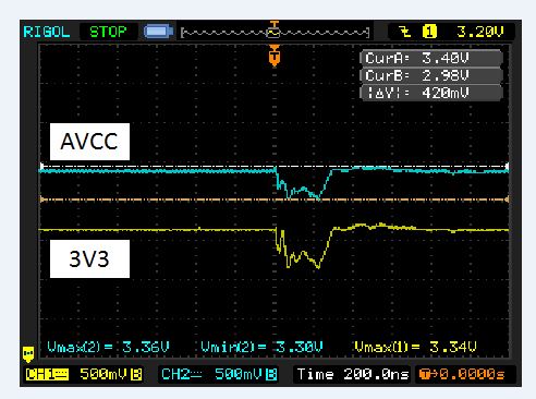
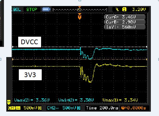
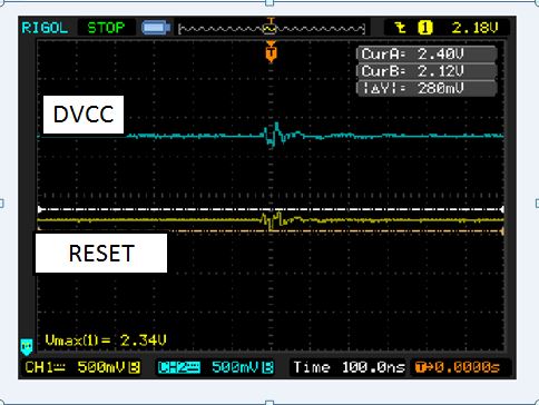
We are using MSP430 in our application.We have captured some dips in AVCC,DVCC and Reset while an inductive load like fan is turned ON/OFF in the vicinity i.e the same 230 volts system in which our system is connected .I have attached the wave-forms below in AVCC,DVCC and Reset pin voltages of controller .

I wanted to know if this will cause any unanimous reset for the controller even this disturbance is for short duration of interms of 100ns.

Appreciate your help at the earliest.

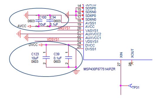
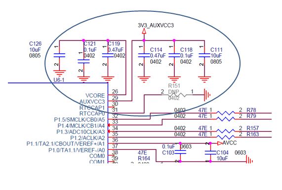
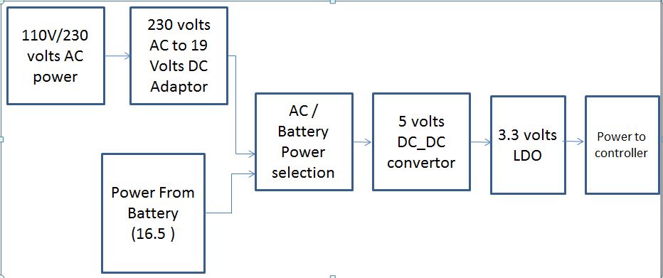
Power Flow to the microcontroller Block diagram :

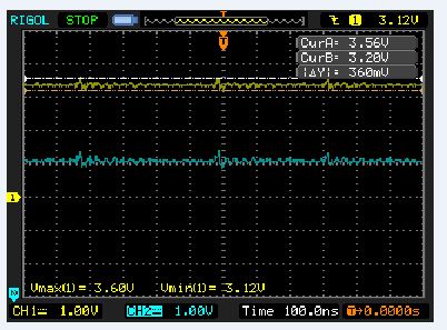
Captured waveform in AVCC :

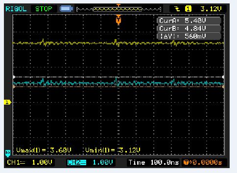
Captured waveform in DVCC :

Captured images on reset line:

Thanks and Regards,

Rajesh K

  • Hi Rajesh, 

    Could you provide the MSP430 variant you are using?

    Best regards, 
    Caleb Overbay

  • Hi Caleb ,

    We are using MSP430F67751A for our application.

    Regards,

    Rajesh

  • Does GND of your device is galvanically isolated from outside world? Any other connections besides scope?

    It could be so that ground of scope is connected to neutral instead of ground/earthing. First thing: use same mains socket to power your design, computer and scope. If it does not help - try to use battery-powered scope or somehow isolate existing scope (using UPS that is disconnected from mains?) and take measurements again. Obviously disconnect your device from computer which possibly is improperly earthed, too.

  • Hi Rajesh,

    First, are you using the recommended capacitance values on you power supply lines?

    There are several things you need to worry about when you see a dip like this in the power supply. The table from Section 5.3 of the datasheet shows the max clock frequencies depending on your Vcc:

    You need to ensure that you are within the appropriate range for operation. 

    I think you may be at risk of the device resetting. It may not be a full reset because the pulse width is less than 2us but it could cause erratic code execution. I recommend checking that the appropriate capacitors are present and if possible change the layout of the board so this dip is not present anymore. 

    Best regards, 

    Caleb Overbay

  • If you observe the same disturbance on the 430 power ground, then you are looking at scope hookup problem. I suspect that this is nothing to be concerned about.

    Peter
  • Hi Caleb ,

    We have checked the capacitors on the AVCC and DVCC in our design and we have provided sufficient capacitors which is more than the recommended in datasheet.

    Refer the below images which will show we have sufficient capacitors on analog and digital and Core and Auxiliary supplies.

    Also in the operating frequency of MCLK of Micro controller is 16MHz and its VCC is 3.3 volts.Hence we are operating in appropriate region.

  • Do you still believe that voltage dip you are seeing on scope is for real? :) I just quickly made illustration of what is most likely going on in your setup, using simple tools - fresh AA battery and wire.

    1. Probe/measure power bus of test device with scope

    2. Connect wire to earthing terminal of scope. If no avail - then ground terminal of test signal output.

    3. For a second or so connect battery between ground of your device and ground of scope. - Yes, battery essentially is shorted through earthing of scope and device, nothing supposedly shall change on the scope screen waveform, right? - Wrong.

    4. Finally - take UPS, power scope through it, disconnect UPS from mains so it runs from battery, make sure that only galvanic connection of scope to outside world (your device) is probe and see that dip is not there

  • Hi llmars,

    I have captured  5 volts and 3.3 volts from our board in scope with our device operating in battery and scope connected in UPS at battery mode.

    In this above test only connection between our board and scope is only the probe used for measuring but We are still seeing noise as mentioned below.

    When I turned on the inductive load in 110 volts which is in no connection with my system and scope.


    Regards,

    Rajesh K.

  • Try this experiment not with your device but for example, measure voltage of LAB power supply while you are switching your inductive load.

    To conclude: it is very unlikely that this is device's (circuit) fault because identical dip in 5V _AND_ 3V bus could be caused only by GND loop through which current spike goes. BUT you say that you disconnected your device and scope from mains. Did you really???  So what remains - problem could be your scope itself or it' s hookup or something else which is hard to see from here.

    Definitely cause could be your AC mains wiring problem like neutral of the load incorrectly connected to earthing, or inductive load you use is actually some powerful EM pulse generator and nothing can stand against it :D

**Attention** This is a public forum