This thread has been locked.

If you have a related question, please click the "Ask a related question" button in the top right corner. The newly created question will be automatically linked to this question.

Setting DCOCLK to 1048576 on MSP432

Other Parts Discussed in Thread: MSP432WARE

Hello,

would like to check the exact how-to for setting DCOCLK to 1048576 on the MSP432.

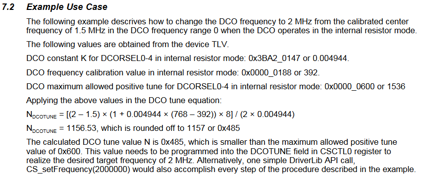
1) Based on what I've read till now, one can set DCO to 1,5/3/6/12/24/48 MHz and to 'tune' it to the exact CLK one desires, one uses DCOTUNE as shown from this document : http://www.ti.com/lit/an/slaa658a/slaa658a.pdf

in which the calculation for DCOTUNE was shown :

But what I am not sure is what are the values I should be inserting into the equation..because I tried setting DCOTUNE as 0x485 to get 2 MHz but it didn't work. Here's the sample code I worked with:

#include "msp.h"
#include <stdint.h>
#define DCOTUNE 0x485
int main(void) {
    volatile uint32_t i;

    WDT_A->CTL = WDT_A_CTL_PW |             // Stop WDT
                 WDT_A_CTL_HOLD;

    P1->DIR |= BIT0;                        // P1.0 set as output

    P4->DIR |= BIT2 | BIT3;
    P4->SEL0 |= BIT2 | BIT3;                // Output ACLK & MCLK
    P4->SEL1 &= ~(BIT2 | BIT3);

    CS->KEY = CS_KEY_VAL;                   // Unlock CS module for register access
    CS->CTL0 = CS_CTL0_DCORSEL_0 | CS_CTL0_DCOTUNE_OFS;
    CS->CTL1 = CS_CTL1_SELA_2 | CS_CTL1_SELS_3 | CS_CTL1_SELM_3;

    CS->KEY = 0;                            // Lock CS module from unintended accesses

    while (1)                               // continuous loop
    {
        P1->OUT ^= BIT0;                    // XOR P1.0
        for (i = 20000; i > 0; i--);        // Delay
    }
}

I got with an OSCI, SMCLK and MCLK = 1.5 MHz, ACLK = ~32 kHz and the led blinks at 1.9 Hz, after having set DCOTUNE for a DCO of 2MHz.

I assume I made a mistake somewhere or perhaps missed a specific line of settings for it?

2) I came across a 2nd possibility in the same document which was to use DriverLib API CS_setFrequency(xxxxxxx) would also work. But does that mean I can just forgo all the usual CS-> Key/CTL0/CTL1 settings with this one line?

3) ALSO what exactly happens when I change __SYSTEM_CLOCK under system_msp432p401r.c? Am I right to assume that changing the CLK there to any specific frequency I want changes the default DCOCLK?


Any help would be appreciated. Thank you very much.

  • Hello Zhek.W,

    I think that you would find it very insightful to look at the API in cs.c found in the content directory (C:\ti\tirex-content\msp\msp432ware__3.50.00.02\driverlib\driverlib\MSP432P4xx). The values for the equation are found in the TLV structure within the device (datasheet Table 6-86, www.ti.com/.../msp432p401r.pdf

    (2) The API includes the necessary settings for to unlock and configure the module. A description and important note about the need to enable FPU is found here:
    dev.ti.com/.../group__cs__api.html

    (3) Yes. In the startup_msp432p401r_ccs.c, you will see that the reset handler calls system_init which is defined in the system_msp432p401r.c and effectively sets the default values before entering main. Please note that this is setup to only support the center frequencies listed (below) and you would still need to use the API or direct register access to tune to alternate frequencies.

    /*--------------------- CPU Frequency Configuration -------------------------*/
    // CPU Frequency
    // <1500000> 1.5 MHz
    // <3000000> 3 MHz
    // <12000000> 12 MHz
    // <24000000> 24 MHz
    // <48000000> 48 MHz
    #define __SYSTEM_CLOCK 3000000


    I hope that is helpful. Please let me know if you have additional questions.
    Chris
  • Hello Chris,

    thanks for your speedy reply and helpful explanation. I will take some time to go through the links you've provided me with. They look like exactly what I've been needing!

    Right off the bat after quickly going through however, would be

    1)  under Table 6.86 I don't seem to find the needed values. Eg. in the datasheet slaa658a, the values for the specific example were given so:

    and the resulting value of DCOTUNE N = 0x485 was what I tried to insert in the code snippet in my 1st post. Could you please take a look at it again and see if there is anything that is blatantly missing to set DCO as 2 MHz?


    Thanks again for pointing me in the right direction. I will read through them thoroughly and get back to you if there are any confusion from my side. Will also be looking through the MSP432 Driver Lib User guide which seems like a goldmine of info.

**Attention** This is a public forum