This thread has been locked.

If you have a related question, please click the "Ask a related question" button in the top right corner. The newly created question will be automatically linked to this question.

MSP430FR2532 : Target Microcontroller is not responding

Other Parts Discussed in Thread: MSP-FET

Hello,

I am trying to establish communication with the MSP430FR2532 on my target board using the Spy-Bi-Wire interface, the MSP-FET programmer and Elprotronic Lite application. When trying to "Verify Security Fuse" in Elpotronic software, I get an error that says that the: Target Microcontroller is not responding. The same error happens when trying to debug using CCS 6.2. I tried multiple voltages with the same result.

Here's my schematic :

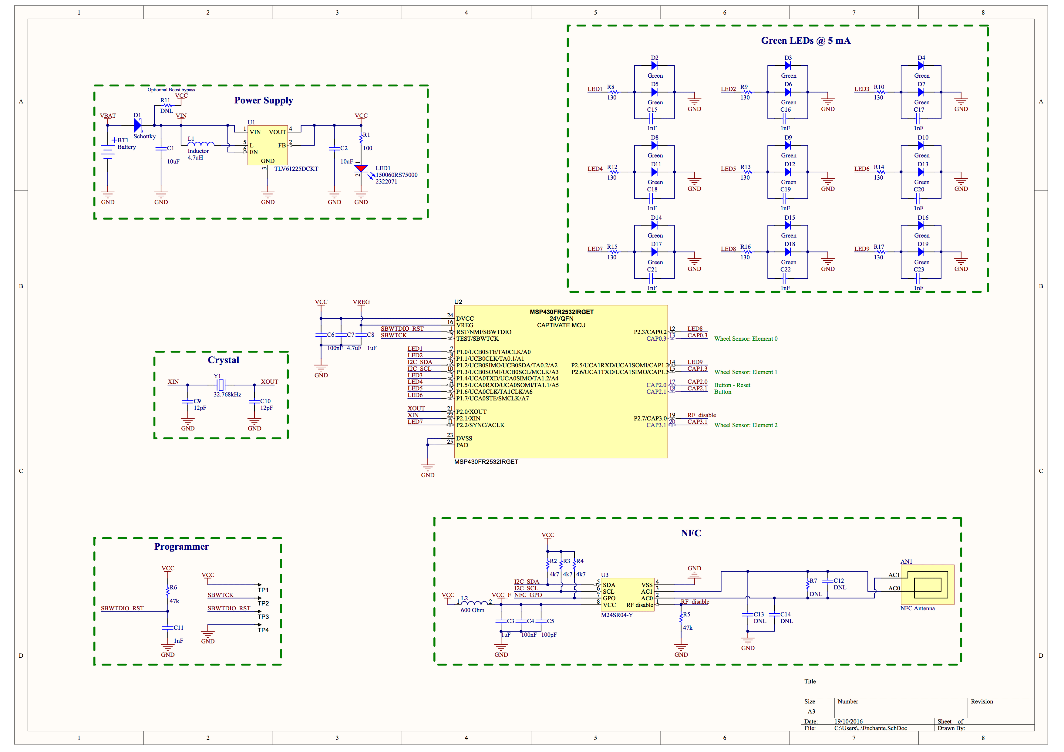
I hand-soldered the components and tried multiple boards with the same result. The one show in the pictures below has only the minimal components soldered: the MCU, C6, C7, R6 and C8. Note that the capacitive pull-down C11 is not soldered.

I checked the continuity from one end of the programmer's ribbon cable to the board connections and it looks fine. I also checked the voltage supplied.

 I'm kind of desperate here since I tried every lead I thought of. Thanks for your help !

  • Hello Badr,

    Thank you for providing this detailed description of your issue. It would definitely appear to be communication failure between the FET and target device. So long as red is Vcc, green is RST, blue is TEST, and black is GND, your FET connections appear to be correct. I appreciate the decoupling capacitor values used and their proximity to the MSP430, as well as the RST passive component values used. My suggestions would be to make the connection between the FET and target MSP430 device as short as possible by any means necessary. Concerning the board layout, the TEST and RST lines should be of similar trace lengths (as short as possible) and not change between board layers. Please provide oscilloscope screenshots of the RST and TEST lines during a communication attempt if the problem persists.

    Regards,
    Ryan
  • Thanks for your feedback Ryan! I checked all the points you've mentionned, everything looks ok. The traces on the PCB are kind of short and symmetric (between TEST and RST), the wires + ribbon are actually much much longer.

    I accidentally solved the issue by externally supplying the 3.3V to the board. It's now flashing perfectly and consistently.

    I'm kind of surprised the MSP-FET doesn't supply enough current. Do you know the actual value it can actually source ?

    Thanks!

    Badr

  • All MSP debug probes can supply targets with up to 100 mA through pin 2 of the 14-pin JTAG connector. But the target should not consume more than 60 mA at peak current, as it may violate the USB specification.

    Regards,
    Ryan

**Attention** This is a public forum