Hi, I use "uart_pc_echo_12mhz" and when I run this program i don't recive any data in putty, and how to change this program to receive a string of data in integer form (1,2,3,4,5,6)?
I have RXD and TXD plugin in my board.
Code for "uart_pc_echo_12mhz" is:
/******************************************************************************
 * MSP432 UART - PC Echo with 12MHz BRCLK
 *
 * Description: This demo echoes back characters received via a PC serial port.
 * SMCLK/DCO is used as a clock source and the device is put in LPM0
 * The auto-clock enable feature is used by the eUSCI and SMCLK is turned off
 * when the UART is idle and turned on when a receive edge is detected.
 * Note that level shifter hardware is needed to shift between RS232 and MSP
 * voltage levels.
 *
 *               MSP432P401
 *             -----------------
 *            |                 |
 *            |                 |
 *            |                 |
 *       RST -|     P1.3/UCA0TXD|----> PC (echo)
 *            |                 |
 *            |                 |
 *            |     P1.2/UCA0RXD|<---- PC
 *            |                 |
 *
 * Author: Timothy Logan
*******************************************************************************/
/* DriverLib Includes */
#include "driverlib.h"

/* Standard Includes */
#include <stdint.h>

#include <stdbool.h>

/* UART Configuration Parameter. These are the configuration parameters to
 * make the eUSCI A UART module to operate with a 9600 baud rate. These
 * values were calculated using the online calculator that TI provides
 * at:
 *software-dl.ti.com/.../index.html
 */
const eUSCI_UART_Config uartConfig =
{
        EUSCI_A_UART_CLOCKSOURCE_SMCLK,          // SMCLK Clock Source
        78,                                     // BRDIV = 78
        2,                                       // UCxBRF = 2
        0,                                       // UCxBRS = 0
        EUSCI_A_UART_NO_PARITY,                  // No Parity
        EUSCI_A_UART_LSB_FIRST,                  // LSB First
        EUSCI_A_UART_ONE_STOP_BIT,               // One stop bit
        EUSCI_A_UART_MODE,                       // UART mode
        EUSCI_A_UART_OVERSAMPLING_BAUDRATE_GENERATION  // Oversampling
};

int main(void)
{
    /* Halting WDT  */
    MAP_WDT_A_holdTimer();

    /* Selecting P1.2 and P1.3 in UART mode */
    MAP_GPIO_setAsPeripheralModuleFunctionInputPin(GPIO_PORT_P1,
            GPIO_PIN1 | GPIO_PIN2 | GPIO_PIN3, GPIO_PRIMARY_MODULE_FUNCTION);

    /* Setting DCO to 12MHz */
    CS_setDCOCenteredFrequency(CS_DCO_FREQUENCY_12);

    /* Configuring UART Module */
    MAP_UART_initModule(EUSCI_A0_BASE, &uartConfig);

    /* Enable UART module */
    MAP_UART_enableModule(EUSCI_A0_BASE);

    /* Enabling interrupts */
    MAP_UART_enableInterrupt(EUSCI_A0_BASE, EUSCI_A_UART_RECEIVE_INTERRUPT);
    MAP_Interrupt_enableInterrupt(INT_EUSCIA0);
    MAP_Interrupt_enableSleepOnIsrExit();
    MAP_Interrupt_enableMaster();

    while(1)
    {
        MAP_PCM_gotoLPM0();
    }
}

/* EUSCI A0 UART ISR - Echoes data back to PC host */
void EUSCIA0_IRQHandler(void)
{
    uint32_t status = MAP_UART_getEnabledInterruptStatus(EUSCI_A0_BASE);

    MAP_UART_clearInterruptFlag(EUSCI_A0_BASE, status);

    if(status & EUSCI_A_UART_RECEIVE_INTERRUPT)
    {
        MAP_UART_transmitData(EUSCI_A0_BASE, MAP_UART_receiveData(EUSCI_A0_BASE));
    }

}
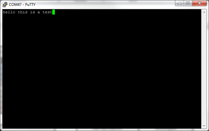
This is putty:
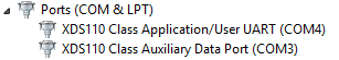
My board: