This thread has been locked.

If you have a related question, please click the "Ask a related question" button in the top right corner. The newly created question will be automatically linked to this question.

MSP430G2553: MSP430 & DS1307 Interfacing Issue

Part Number: MSP430G2553
Other Parts Discussed in Thread: ENERGIA

Dear All,

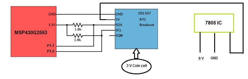
I am developing a timer controlled home appliance using MSP430G2553 uc and DS1307 RTC module. I have done the code in energia and uploaded into the MSP430 and monitored through serial monitor.

Unfortunately it was showing like,

2000/0/0 0:0:0 

2000/0/0 0:0:0 

2000/0/0 0:0:0 

Here is my code,

#include <Wire.h>
#include <RTClib.h>

RTC_DS1307 RTC;
void setup () {
Serial.begin(9600);
Wire.begin();
RTC.begin();

if ( RTC.isrunning()) {
Serial.println("RTC is NOT running!");

// following line sets the RTC to the date & time this sketch was compiled
RTC.adjust(DateTime(__DATE__, __TIME__));
}
}
void loop () {

DateTime now = RTC.now();
Serial.print(now.year(), DEC);
Serial.print('/');
Serial.print(now.month(), DEC);
Serial.print('/');
Serial.print(now.day(), DEC);
Serial.print(' ');
Serial.print(now.hour(), DEC);
Serial.print(':');
Serial.print(now.minute(), DEC);
Serial.print(':');
Serial.print(now.second(), DEC);
Serial.println();

delay(3000);
}


I have used 2 numbers of 1.7 k ohm resistors as pull up for both SCL and SDA.

Your valuable support is required.

  • This is the expected result of a faulty connection between the LaunchPad and DS1307, or if the DS1307 is not being powered properly. Please make sure P1.6 is connected to the SCL and P1.7 to the SDA, and that the LED2 jumper is disconnected. Also confirm that the DS1307 is being supplied the correct voltage.

    Regards,
    Ryan
  • Thank you Mr. Ryan for your quick response.

    I have checked all the connection found to be OK. 

    LED2 jumper also in open condition, 3V coin cell is available in the DS1307 kit.

    When i measured voltage across SCLand SDA pin of DS1307 with respect to ground and found to be 4v in both pins.

    Please find below my circuit diagram.

    Please note that even if i remove DS1307 kit from circuit then also i am getting the value like,

    2000/0/0 0:0:0 , so as you said i am agree that DS1307 is not communicating, but how to make it working?

    Kindly support to fix this issue. 

    Regards,

    HASEEL

  • MSP430 devices do not support pin voltages greater than 3.6 V, so your comment that the I2C lines are 4 V is a cause for concern. If the I2C lines of the DS1307 operate at 5 V (supply voltage of the device itself) then you will need to use an I2C isolator or voltage level translator to compensate.

    Regards,
    Ryan
  • Voltage level difference should not cause an issue. Since your pull-up is to 3.3V, there is no way SCL or SDA measuring 4V- suspecting some failure in RTC chip. The Vih min of DS1307 is 2.2V from datasheet. So with 3.3V pullup it should work. Btw what is the I2C frequency?

**Attention** This is a public forum