This thread has been locked.

If you have a related question, please click the "Ask a related question" button in the top right corner. The newly created question will be automatically linked to this question.

MSP432P401R: Please help to figure out the relationship between ADC14 sampling time and maximum speed in MSPS.

Part Number: MSP432P401R

Hello friends! Sorry beforehand if I am asking something silly, I am new to programming and at all, I am a pianist. So electronics is my self-learnt thing and of course I suck in math.

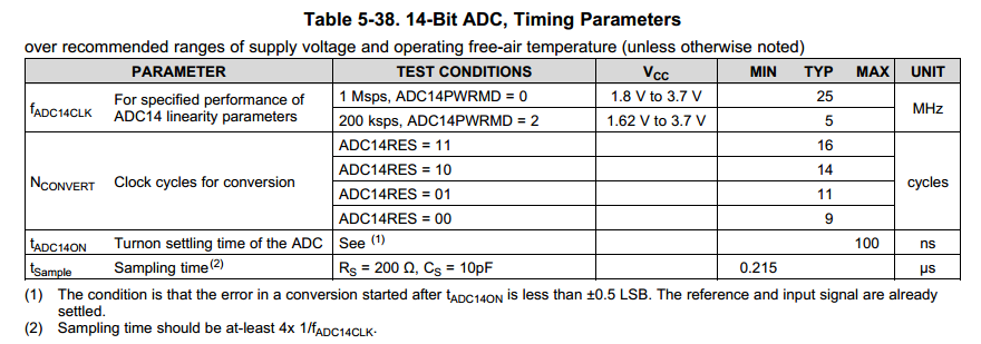
So I have been reading the manual on the ADC14 in MSP432 mcus. The manual says, that in active mode, the maximum speed is 1Msps. Later, the manual explains how to adjust sampling time, and how to calculate the Total Sampling Time of a single conversion. Approximately something like sampling time+16 clock cycles for the actual conversion. Now, could anybody please explain, how this maximum speed of 1Msps and Total Sampling Time are related? Does that "maximum speed" thing mean that my Total Sampling Time must be no shorter, than 0,000001s? Or does it mean, that my Total Sampling Time can be as short as I wish, but I must make no more, than 1000000 of conversions per second? 

I understand that apparently it is something very obvious and simple, but since I am a musician I really suck. So please don't get angry at my stupidness and I will say many thanks for helping me to rectify my brains here :)

  • Besides manual, datasheet is also important to read. Datasheet specify minimum sampling time you are looking for, 0.215 us. Datasheet does not specify 1MSPS as maximum ADC sample rate actually, it (1MSPS) is mentioned in the device overview which is not specs. Go figure.

  • Many thanks!! Merry coming Christmas.
  • Stanislav,

    Many of Ilmars points are very well written. However, I would add a few things. The ADC14's max sample rate is 1MSPS so the calculation is a bit off. ADC14 also requires a trigger and setup/hold time. The 16 cycles is only the conversion. There is also another cycle associated with the transfer to the memory register. A proper calculation will include the sample and conversion times together to get a full idea of how fast you can operate at. Reference the TRM to have an idea on the different sample modes as well as the conversion memory. Sections 20.2.6.1 and 20.2.6.2 give some more insight on the modes.

    Use both the TRM and the datasheet in conjunction together to get a better idea of your max capabilities! :)

  • Evan Wakefield said:
    A proper calculation will include the sample and conversion times together to get a full idea of how fast you can operate at.

    Good. Could you please show example of proper calculation? - for someone who needs single channel continuous sampling mode w/o using timer for triggering. Let's say I need to sample around 200KSps, bandwidth of interest is 50KHz (yes, it's half of Nyquist freq).

  • You may find the examples in this thread helpful.

    e2e.ti.com/.../2023396

    Regards,
    Chris
  • Chris Sterzik said:
    You may find the examples in this thread helpful.

    Not quite. There's timer involved which is not what I asked for: "continuous sampling mode w/o using timer".

    Again would be good that following txt is supplied with example calculation:

    ADC14 also requires a trigger and setup/hold time. The 16 cycles is only the conversion. There is also another cycle associated with the transfer to the memory register. A proper calculation will include the sample and conversion times together to get a full idea of how fast you can operate at. 

  • Moving to a non-timer example would require the two API's to be changed from

        * Configuring the sample trigger to be sourced from Timer_A0 CCR1 and on the

        * rising edge, default samplemode is extended (SHP=0)

        */

       MAP_ADC14_setSampleHoldTrigger(ADC_TRIGGER_SOURCE1, false);

       /*

        * Set SHP=1 for pulse sample mode, and set length to 4 clocks, the ADC

        * is manually triggered from the timer

        */

       MAP_ADC14_enableSampleTimer(ADC_MANUAL_ITERATION);

    to

      /*

        * Configuring the sample trigger to be sourced from a sw trigger and on the

        * rising edge, default samplemode is extended (SHP=0)

        */

       MAP_ADC14_setSampleHoldTrigger(ADC_TRIGGER_ADCSC, false);

       /*

        * Set SHP=1 for pulse sample mode, and set length to 4 clocks, the ADC

        * is manually triggered from the timer

        */

       MAP_ADC14_enableSampleTimer(ADC_AUTOMATIC_ITERATION);

    Hopefully this is more clear in this attached example.  I have also put in a request to add more comments around the number of cycles.


    Regards,

    Chris

    /*
     * -------------------------------------------
     *    MSP432 DriverLib - v3_10_00_09 
     * -------------------------------------------
     *
     * --COPYRIGHT--,BSD,BSD
     * Copyright (c) 2014, Texas Instruments Incorporated
     * All rights reserved.
     *
     * Redistribution and use in source and binary forms, with or without
     * modification, are permitted provided that the following conditions
     * are met:
     *
     * *  Redistributions of source code must retain the above copyright
     *    notice, this list of conditions and the following disclaimer.
     *
     * *  Redistributions in binary form must reproduce the above copyright
     *    notice, this list of conditions and the following disclaimer in the
     *    documentation and/or other materials provided with the distribution.
     *
     * *  Neither the name of Texas Instruments Incorporated nor the names of
     *    its contributors may be used to endorse or promote products derived
     *    from this software without specific prior written permission.
     *
     * THIS SOFTWARE IS PROVIDED BY THE COPYRIGHT HOLDERS AND CONTRIBUTORS "AS IS"
     * AND ANY EXPRESS OR IMPLIED WARRANTIES, INCLUDING, BUT NOT LIMITED TO,
     * THE IMPLIED WARRANTIES OF MERCHANTABILITY AND FITNESS FOR A PARTICULAR
     * PURPOSE ARE DISCLAIMED. IN NO EVENT SHALL THE COPYRIGHT OWNER OR
     * CONTRIBUTORS BE LIABLE FOR ANY DIRECT, INDIRECT, INCIDENTAL, SPECIAL,
     * EXEMPLARY, OR CONSEQUENTIAL DAMAGES (INCLUDING, BUT NOT LIMITED TO,
     * PROCUREMENT OF SUBSTITUTE GOODS OR SERVICES; LOSS OF USE, DATA, OR PROFITS;
     * OR BUSINESS INTERRUPTION) HOWEVER CAUSED AND ON ANY THEORY OF LIABILITY,
     * WHETHER IN CONTRACT, STRICT LIABILITY, OR TORT (INCLUDING NEGLIGENCE OR
     * OTHERWISE) ARISING IN ANY WAY OUT OF THE USE OF THIS SOFTWARE,
     * EVEN IF ADVISED OF THE POSSIBILITY OF SUCH DAMAGE.
     * --/COPYRIGHT--*/
    /*******************************************************************************
     * MSP432 ADC14 - Single Channel Continuous Sample w/ Timer_A Trigger
     *
     * Description: In this ADC14 code example, a single input channel is sampled
     * using the standard 3.3v reference. The ADC is setup to continuously
     * sample/convert from A0 when the sw trigger starts and the DMA is configured
     * to trigger from the ADC and move the results into a ping-pong buffer. The
     * sample time is set to 4 + 1 ADC clocks and the conversion time is 16 clocks,
     * one additional clock is needed for the memory transfer within the ADC.
     * The effective sampling rate is 22 clocks or 22/24Mhz = 917ns.
     *
     * The PWM is started once the GPIO interrupt for P1.1 is serviced.
     *
     *                MSP432P401
     *             ------------------
     *         /|\|                  |
     *          | |                  |
     *          --|RST         P5.5  |<--- A0 (Analog Input)
     *            |                  |
     *            |            P1.1  |<--- GPIO trigger to Start conversions
     *            |                  |
     *            |            P1.0  |---> Debug port to show DMA ISR
     *            |                  |
     *
     * Author: Timothy Logan/ C. Sterzik
     ******************************************************************************/
    /* DriverLib Includes */
    #include "driverlib.h"
    
    /* Standard Includes */
    #include <stdint.h>
    #include <stdbool.h>
    
    #define ARRAY_LENGTH	256
    
    /* DMA Control Table */
    #if defined(__TI_COMPILER_VERSION__)
    #pragma DATA_ALIGN(MSP_EXP432P401RLP_DMAControlTable, 1024)
    #elif defined(__IAR_SYSTEMS_ICC__)
    #pragma data_alignment=1024
    #elif defined(__GNUC__)
    __attribute__ ((aligned (1024)))
    #elif defined(__CC_ARM)
    __align(1024)
    #endif
    static DMA_ControlTable MSP_EXP432P401RLP_DMAControlTable[16];
    
    /* Statics */
    static volatile uint16_t resultsBufferPrimary[ARRAY_LENGTH];
    static volatile uint16_t resultsBufferAlternate[ARRAY_LENGTH];
    
    int main(void)
    {
        /* Halting WDT  */
        MAP_WDT_A_holdTimer();
        MAP_Interrupt_enableSleepOnIsrExit();
    
        /* Starting HFXT in non-bypass mode without a timeout. Before we start
          * we have to change VCORE to 1 to support the 48MHz frequency */
    //    MAP_PCM_setCoreVoltageLevel(PCM_VCORE1);
    //    MAP_FlashCtl_setWaitState(FLASH_BANK0, 2);
    //    MAP_FlashCtl_setWaitState(FLASH_BANK1, 2);
    
        /*
         * Revision C silicon supports wait states of 1 at 48Mhz
         */
        MAP_PCM_setCoreVoltageLevel(PCM_VCORE1);
        MAP_FlashCtl_setWaitState(FLASH_BANK0, 1);
        MAP_FlashCtl_setWaitState(FLASH_BANK1, 1);
    
        /*
         * Setting up clocks
         * MCLK = MCLK = 48MHz
         * SMCLK = MCLK/2 = 24Mhz
         * ACLK = REFO = 32Khz
         */
        MAP_CS_setDCOFrequency(48000000);
        MAP_CS_initClockSignal(CS_ACLK, CS_REFOCLK_SELECT, CS_CLOCK_DIVIDER_1);
        MAP_CS_initClockSignal(CS_SMCLK, CS_DCOCLK_SELECT, CS_CLOCK_DIVIDER_2);
        MAP_CS_initClockSignal(CS_MCLK, CS_DCOCLK_SELECT, CS_CLOCK_DIVIDER_1);
    
        /* Initializing ADC (SMCLK/1/1) */
        MAP_ADC14_enableModule();
        MAP_ADC14_initModule(ADC_CLOCKSOURCE_SMCLK, ADC_PREDIVIDER_1, ADC_DIVIDER_1,
                0);
    
        /*
         * Debug
         * Configuring P1.0 as output
         */
        MAP_GPIO_setAsOutputPin(GPIO_PORT_P1, GPIO_PIN0);
        P1OUT &= ~BIT0;
    
        /*
         * Configuring GPIOs (5.5 A0)
         */
        MAP_GPIO_setAsPeripheralModuleFunctionInputPin(GPIO_PORT_P5, GPIO_PIN5,
        GPIO_TERTIARY_MODULE_FUNCTION);
    
        /*
         * Configuring P1.1 as an input and enabling interrupt, the timer is started from
         * GPIO ISR.
         */
        MAP_GPIO_setAsInputPinWithPullUpResistor(GPIO_PORT_P1, GPIO_PIN1);
        MAP_GPIO_interruptEdgeSelect(GPIO_PORT_P1,GPIO_PIN1,GPIO_HIGH_TO_LOW_TRANSITION);
        MAP_GPIO_clearInterruptFlag(GPIO_PORT_P1, GPIO_PIN1);
        MAP_GPIO_enableInterrupt(GPIO_PORT_P1, GPIO_PIN1);
    
        /*
         * Configuring ADC Memory, repeat-single-channel, A0
         */
        MAP_ADC14_configureSingleSampleMode(ADC_MEM0, true);
    
        /*
         * Configuring ADC Memory, reference, and single ended conversion
         * A0 goes to mem0, AVcc is the reference, and the conversion is
         * single-ended
         */
        MAP_ADC14_configureConversionMemory(ADC_MEM0, ADC_VREFPOS_AVCC_VREFNEG_VSS,
        ADC_INPUT_A0, false);
        /*
         * Configuring the sample trigger to be sourced from a sw trigger and on the
         * rising edge, default samplemode is extended (SHP=0)
         */
        MAP_ADC14_setSampleHoldTrigger(ADC_TRIGGER_ADCSC, false);
    
        /*
         * Set SHP=1 for pulse sample mode, and set length to 4 clocks, the ADC
         * is manually triggered from the timer
         */
        MAP_ADC14_enableSampleTimer(ADC_AUTOMATIC_ITERATION);
        MAP_ADC14_setSampleHoldTime(ADC_PULSE_WIDTH_4,ADC_PULSE_WIDTH_4);
    
        /* Configuring DMA module */
        MAP_DMA_enableModule();
        MAP_DMA_setControlBase(MSP_EXP432P401RLP_DMAControlTable);
    
        /*
         * Setup the DMA + ADC14 interface
         */
        MAP_DMA_disableChannelAttribute(DMA_CH7_ADC14,
                                     UDMA_ATTR_ALTSELECT | UDMA_ATTR_USEBURST |
                                     UDMA_ATTR_HIGH_PRIORITY |
                                     UDMA_ATTR_REQMASK);
    
        /*
         * Setting Control Indexes. In this case we will set the source of the
         * DMA transfer to ADC14 Memory 0 and the destination to the destination
         * data array.
         */
        MAP_DMA_setChannelControl(UDMA_PRI_SELECT | DMA_CH7_ADC14,
        		UDMA_SIZE_16 | UDMA_SRC_INC_NONE | UDMA_DST_INC_16 | UDMA_ARB_1);
        MAP_DMA_setChannelTransfer(UDMA_PRI_SELECT | DMA_CH7_ADC14,
        		UDMA_MODE_PINGPONG, (void*) &ADC14->MEM[0],
    			(void*)resultsBufferPrimary, ARRAY_LENGTH);
        MAP_DMA_setChannelControl(UDMA_ALT_SELECT | DMA_CH7_ADC14,
        		UDMA_SIZE_16 | UDMA_SRC_INC_NONE | UDMA_DST_INC_16 | UDMA_ARB_1);
        MAP_DMA_setChannelTransfer(UDMA_ALT_SELECT | DMA_CH7_ADC14,
        		UDMA_MODE_PINGPONG, (void*) &ADC14->MEM[0],
    			(void*)resultsBufferAlternate, ARRAY_LENGTH);
    
        /* Assigning/Enabling Interrupts */
        MAP_DMA_assignInterrupt(DMA_INT1, 7);
        MAP_DMA_assignChannel(DMA_CH7_ADC14);
        MAP_DMA_clearInterruptFlag(7);
    
        /* Enabling Interrupts */
        MAP_Interrupt_enableInterrupt(INT_DMA_INT1);
        MAP_Interrupt_enableInterrupt(INT_PORT1);
        MAP_Interrupt_enableMaster();
    
        /* Going to sleep */
        MAP_PCM_gotoLPM0();
        __no_operation();
    }
    
    /* Completion interrupt for ADC14 MEM0 */
    __attribute__((ramfunc))  // Requires compiler TI v15.12.1.LTS
    void DMA_INT1_IRQHandler(void)
    {
        P1->OUT |= BIT0;
        /*
         * Switch between primary and alternate bufferes with DMA's PingPong mode
         */
        if (MAP_DMA_getChannelAttribute(7) & UDMA_ATTR_ALTSELECT)
        {
    //        MAP_DMA_setChannelControl(UDMA_PRI_SELECT | DMA_CH7_ADC14,
    //        		UDMA_SIZE_16 | UDMA_SRC_INC_NONE | UDMA_DST_INC_16 | UDMA_ARB_1);
    //        MAP_DMA_setChannelTransfer(UDMA_PRI_SELECT | DMA_CH7_ADC14,
    //        		UDMA_MODE_PINGPONG, (void*) &ADC14->MEM[0],
    //    			resultsBufferPrimary, ARRAY_LENGTH);
        	MSP_EXP432P401RLP_DMAControlTable[7].control =
        			(MSP_EXP432P401RLP_DMAControlTable[7].control & 0xff000000 ) |
    				(((ARRAY_LENGTH)-1)<<4) | 0x03;
        }
        else
        {
    //        MAP_DMA_setChannelControl(UDMA_ALT_SELECT | DMA_CH7_ADC14,
    //        		UDMA_SIZE_16 | UDMA_SRC_INC_NONE | UDMA_DST_INC_16 | UDMA_ARB_1);
    //        MAP_DMA_setChannelTransfer(UDMA_ALT_SELECT | DMA_CH7_ADC14,
    //        		UDMA_MODE_PINGPONG, (void*) &ADC14->MEM[0],
    //    			resultsBufferAlternate, ARRAY_LENGTH);
    
            /*
             * disabling conversions
             */
            MAP_ADC14_disableConversion();
            MAP_DMA_disableChannel(7);
            /*
             * ISR is being called twice at the end.  Need to investigate further.
             */
            MAP_DMA_clearInterruptFlag(7);
        	MSP_EXP432P401RLP_DMAControlTable[15].control =
        			(MSP_EXP432P401RLP_DMAControlTable[15].control & 0xff000000 ) |
    				(((ARRAY_LENGTH)-1)<<4) | 0x03;
        }
        P1->OUT &= ~BIT0;
    }
    
    void PORT1_IRQHandler(void)
    {
        P1->OUT |= BIT0;
        P1IFG &= ~BIT1;
        /*
         * enabling conversions
         */
        MAP_ADC14_enableConversion();
        MAP_DMA_enableChannel(7);
        MAP_ADC14_toggleConversionTrigger();
        P1->OUT &= ~BIT0;
    }
    

  • Hello Chris,

    Thank you, description in the source code (below) answers question, thou would be good if User Manual is updated accordingly. At the moment documentation is missing this important piece of information. 

    /*******************************************************************************
     * MSP432 ADC14 - Single Channel Continuous Sample w/ Timer_A Trigger
     *
     * Description: In this ADC14 code example, a single input channel is sampled
     * using the standard 3.3v reference. The ADC is setup to continuously
     * sample/convert from A0 when the sw trigger starts and the DMA is configured
     * to trigger from the ADC and move the results into a ping-pong buffer. The
     * sample time is set to 4 + 1 ADC clocks and the conversion time is 16 clocks,
     * one additional clock is needed for the memory transfer within the ADC.
     * The effective sampling rate is 22 clocks or 22/24Mhz = 917ns.
     *
     * The PWM is started once the GPIO interrupt for P1.1 is serviced.
     */
    

  • Illmars,

    Thanks for the feedback on the documentation. We are definitely always looking for ways to improve our documentation and we will take this and try and incorporate it into the documentation moving forward. Give us a little time though with the holidays :) If you have any other questions or feedback, definitely let us know! Happy holidays!
  • So, if I understand correctly, the total time is (sampling time+1 cycle)+(conversion time+1 cycle). Thank you everybody and happy holidays!

**Attention** This is a public forum