This thread has been locked.

If you have a related question, please click the "Ask a related question" button in the top right corner. The newly created question will be automatically linked to this question.

MSP-EXP430FR6989: OutOfBox Demo LCD HAL C code

Part Number: MSP-EXP430FR6989

Hello!

I'm a beginner to the MSP430FR series as well as the LCD module that came along with the LaunchPad.

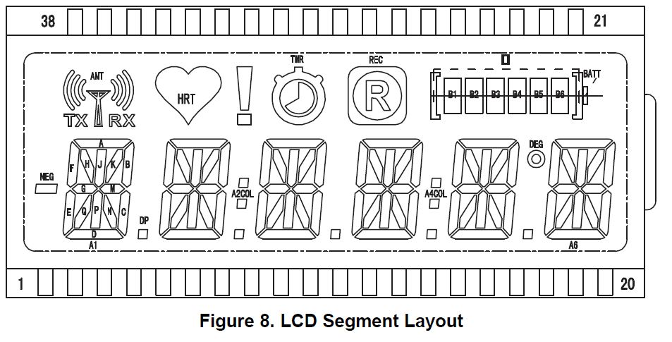
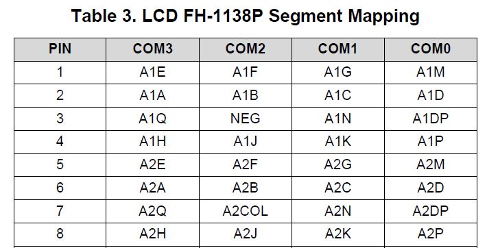
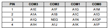
While I'm trying to learn the source code (hal_LCD.c), I do not quite understand what the values represent in the second column in the 2D arrays:  (I do know where to get the values for the first column)

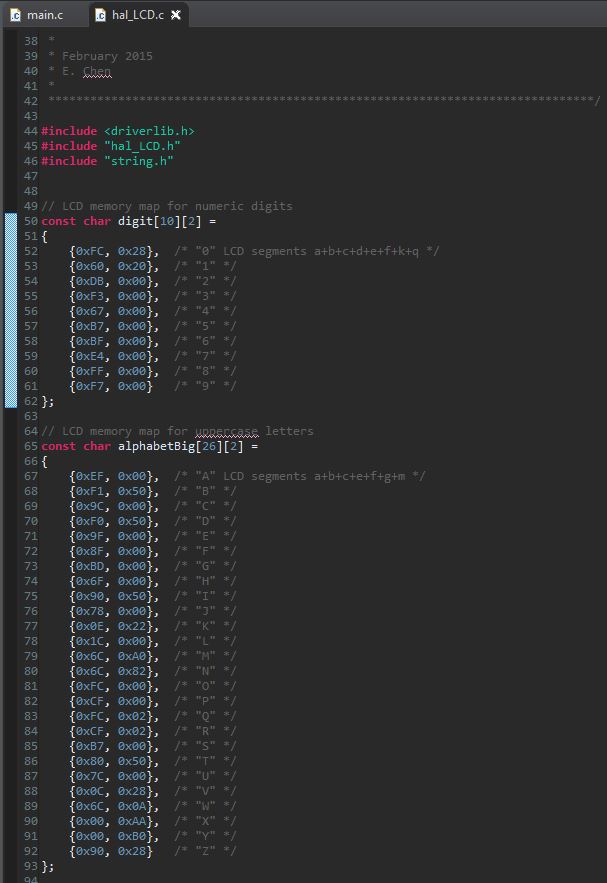
Can someone please drop some hints on this?

Thanks!

  • Hi Kenneth,

    Thanks for posting!


    If you see Figure 8 LCD Segment Layout,

    as well as Table 3 LCD FH-1138P Segment Mapping

    in the MSP-EXP430FR6989 Launchpad User's Guide www.ti.com/.../slau627, you can observe that for each digit on the display, there are a total of 4 pins (4 rows of the mapping) to control every segment in that digit.

    So for example, the A1 digit on the left side of the display is controlled by pins 1-4, the first 4 rows of the table. Each row represents 4 bits of data to control it (the 4 columns), for 16-bits total to control the entire digit. This is why 2 bytes are needed to fully set each digit. You can see from the mapping table and the segment layout, that the primary segments to display something are mostly stored in the first 2 rows = first byte. But some letters, e.g. the letter K, use the diagonal segments - you can see that these diagonal segments, e.g. A1K and A1N, are in the 3rd and 4th rows = second byte.

    Does this help to clear things up?

    Regards,
    Katie

  • Hello Kenneth,

    On the MSP-EXP430FR6989 LaunchPad User's Guide (http://www.ti.com/lit/ug/slau627a/slau627a.pdf) Table 3 on Page 12 there is a list of the LCD segments for each Digit. On there, each Digit has an ending character to it that designates which segment will light up. Those are what are used to map out the two columns.

    For example, here is the mapping for Digit A1 

    This is used to map out hex digits in the hal_LCD file.

    The first hex digit "column 1" is mapped to match with A/B/C/D and E/F/G/M (Pin 2 and 1 for Digit A1)

    The second hex digit "column 2" is mapped to match with H/J/K/P and Q/*/N/DP (Pin 4 and 3 for Digit A1)

    Note: The * marker is for the COM2 segments which vary based on the Pin. For the image above, that would be NEG.

    Based on this, let's look at the first entry of the digit[10][2] array which is 0xFC and 0x28.

    0xFC = 1111 1100, which when compared with A/B/C/D and E/F/G/M results in A+B+C+D+E+F

    0x28 = 0010 1000, which when compared with H/J/K/P and Q/*/N/DP results in K+Q

    Hence the comment of a+b+c+d+e+f+k+q.

    Does this make sense now?

  • Thank you Katie and Ralph!

    I understand now and just realized that 0 has that diagonal line (segments k+q) in order to differentiate from a letter O that's why I stumbled on the 0x28 part but I see it clearly now.

    Thanks again!

    -Kenneth
  • I'm glad we could help!
    Regards,
    Katie

**Attention** This is a public forum