


Hi,
When's the correct time to set a repeated start command for the USCIB0 in I2C mode? When I set UCTXSTT=1 during the TX ISR, the system issues a repeated start before transmitting the data, even though the state diagram shows it should issue the start afterwards. See diagram.

What I'm trying to do in the TX ISR is:
1. put data into UCB0TXBUF
2. change slave address
3. set UCTR = 1 or UCTR = 0, depending upon my needs for the next command
4. set UCTXSTT=1
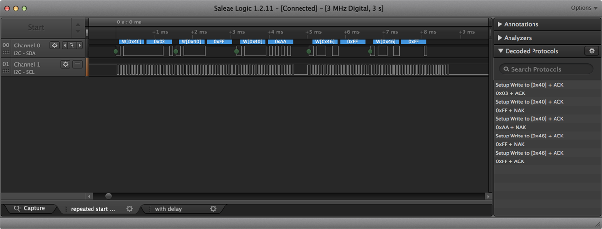
But this just produces a repeated start before sending the data and also skips about half of the data (see IMAGE 1 below).
I'm attempting to send this message:
    		0x0040>>1 	| IO::USCI_I2C::ADDR,	// set address
    		0x0003 		| IO::USCI_I2C::WRITE,	// set ptr
    		0x00FF 		| IO::USCI_I2C::WRITE,	// write to register
		0x0040>>1	| IO::USCI_I2C::ADDR,	// set address
    		0x0001 		| IO::USCI_I2C::WRITE,	// set ptr
    		0x00AA 		| IO::USCI_I2C::WRITE,	// write to register

    		0x0046>>1 	| IO::USCI_I2C::ADDR,	// set address
    		0x0003 		| IO::USCI_I2C::WRITE,	// set ptr
    		0x00FF 		| IO::USCI_I2C::WRITE,	// write to register
		0x0046>>1	| IO::USCI_I2C::ADDR,	// set address
    		0x0001 		| IO::USCI_I2C::WRITE,	// set ptr
    		0x00AA 		| IO::USCI_I2C::WRITE	// write to register
IMAGE 1: Here's the capture without a delay (incorrect):
I found that if I add a delay in the ISR, the data is in fact transmitted and then the start is issued.
	// 3. RESTART w/ new address
	else if(isAddr(nextCmd))
	{
		UCB0I2CSA = (uint8_t)nextCmd;
		/* "Setting UCTXSTT generates a repeated START condition. In this case,
		 UCTR may be set or cleared to configure transmitter or receiver,
		 and a different slave address may be written into UCBxI2CSA, if
		 desired." */
		// to accomplish this, send a start write or start read command
		// this will set the UCTR flag appropriately and set the start bit

		// increment counter past address cmd to get to next rd/wr command
		// (we need to peek to see if it's a read or a write).
		_delay_cycles(2000); // with this, the code will execute as expected, issuing a start AFTER the data is transmitted
		nextCmd = seq[++seqCtr];
		if(isWrite(nextCmd)) startWr();
		else if(isRead(nextCmd)) startRd();
	}
Code on github:  github.com/.../cribbage_LED
Here's a capture with delay (correct)

Here's my ISR an accompanying code.
/*	USCII2C.h
 *  Created on: Dec 26, 2016
 *      Author: benny		 */
#ifndef USCII2C_H_
#define USCII2C_H_

// include to use standard types
#include <stdint.h>

namespace IO
{
	class USCI_I2C
	{
	public:
		// used as bitmasks to check addresses
		enum TRANSACTION_TYPE {
			ADDR = 1<<8,
			READ = 1<<9,
			WRITE = 1<<10
		};
		// maybe try this later to replace TRANSACTION_TYPE
//		union I2C_TRANSACTION
//		{
//			uint16_t packet;
//			uint8_t data;
//			uint8_t isAddr:	1;
//			uint8_t isRd: 	1;
//			uint8_t isWr: 	1;
//		};
		USCI_I2C();
		// initialize the I2C hardware and member variables
		// currently just use MCLK as the clock source
		// busy counts will prevent an infinite loop if the bus becomes permanently busy
		// set to -1 to disable.
		void init(double F_MCLK, double F_I2C, uint8_t defaultAddress,
				unsigned busyCnts = 0, volatile unsigned char *SEL_PORT = 0,
				uint8_t PINS = 0);
		//
		void transaction(uint16_t *seq, uint16_t seqLen,
				uint8_t *recvData, uint16_t wakeupSRBits);
		// Use this to check whether a previously scheduled I2C sequence has been
		// fully processed.
		inline bool done() { return(state == IDLE); };
		// returns true if an acknowledge was received for the given address
		// ported from TI_USCI_I2C_slave_present
		// 	- made to work for eUSCI
		//	- replaced master-slave terminology w/ coordinator-client
		bool checkAddr(uint8_t addr);
		// used by ISR
		inline void handleTxRxInt(bool isWrInt);
		inline void startSeq();
	private:
		// check the flag set in the data packet
		inline bool isAddr(uint16_t seq)	{ return seq & ADDR; };
		inline bool isWrite(uint16_t seq) 	{ return seq & WRITE; };
		inline bool isRead(uint16_t seq) 	{ return seq & READ; };
		// start a write command (Coordinator-sender)
		inline void startWr();
		// start a read command (Coordinator-receiver)
		inline void startRd();
		inline void waitForBusFree();

		// used by the state machine
		// set even values to each state to allow quick processing
		// in ISR using the __even_in_range intrinsic
		// TODO: do I need this, or was this just for USI?
		enum STATE {
			IDLE = 0,
			START = 2,
			PREPARE_ACKNACK = 4,
			HANDLE_RXTX = 6,
			RECEIVED_DATA = 8,
			PREPARE_STOP = 10,
			STOP = 12
		} state;
		uint8_t defAddr;	// default I2C address
		uint16_t *seq;
		uint16_t seqLen, seqCtr;
		uint8_t *recvData;
		uint16_t wakeupSRBits;
		unsigned busyCnts;
	};
	// externally defined object required for use in the interrupt
	extern USCI_I2C i2c;
} /* namespace IO */

#endif /* USCII2C_H_ */
/* 	USCII2C.cpp
 *  Created on: Dec 26, 2016
 *      Author: benny
 */
// include msp430 header to get access to USCI registers
#include "msp430.h"
#include "USCII2C.h"
#include <cassert>
#include <stdio.h>

IO::USCI_I2C::USCI_I2C()
{
	this->state = IDLE;
}
void IO::USCI_I2C::init(double F_MCLK, double F_I2C, uint8_t defaultAddress,
		unsigned busyCnts, volatile unsigned char *SEL_PORT, uint8_t PINS)
{
	this->busyCnts = busyCnts;
	if(this->busyCnts == 0) this->busyCnts = 1;
	this->defAddr = defaultAddress;
	// configure I2C pins, e.g. P1SEL1 |= (BIT6 | BIT7)
	*SEL_PORT |= PINS;
	// put eUSCI_B in reset state while we config it
	UCB0CTLW0 = UCSWRST;
	// use SMCLK as clock source, I2C Mode, send I2C stop
	UCB0CTLW0 |= UCMODE_3 | UCMST | UCSSEL__SMCLK;
	assert(F_MCLK/F_I2C > 1);
	UCB0BRW = F_MCLK/F_I2C;	// set I2C frequency
	UCB0I2CSA = defaultAddress; 	// client address
	UCB0CTLW0 &= ~UCSWRST; 	// put eUSCI_B in operational state
	// enable TX interrupt and NACK interrupt
	UCB0IE |= UCTXIE0 | UCNACKIE;
}

void IO::USCI_I2C::waitForBusFree() {
	unsigned cnt = 0;
	while (UCB0STAT & UCBBUSY)
	{
		// increment counter
		busyCnts++;
		// if counter hits threshold, alert user
		if(cnt == busyCnts)
		{
			printf("oops! I2C bus frozen\n");
			assert(0);
		}
	}
}

void IO::USCI_I2C::transaction(uint16_t *seq, uint16_t seqLen,
		uint8_t *recvData, uint16_t wakeupSRBits)
{
	// we can't start another sequence until the current one is done
	if(UCB0STAT & UCBBUSY)
		// send a stop
		UCB0CTLW0 |= UCTXSTP;
	waitForBusFree();
	// load the sequence into the library:
	assert(seq);	// ensure we have a sequence
	this->seq = seq;
	assert(seqLen);	// ensure we have a seqLength
	this->seqLen = seqLen;
	// no assert, could be a null ptr iff only writing
	this->recvData = recvData;
	// no assert, could not be waking up
	this->wakeupSRBits = wakeupSRBits;
	// update status
	seqCtr = 0;
	state = START;
	// start the sequence transmission, trigger, but don't set data yet
	startSeq();
	// exit and handle the transaction from interrupts
}
inline void IO::USCI_I2C::startWr()
{
	UCB0CTLW0 |= UCTR | UCTXSTT;
}
inline void IO::USCI_I2C::startRd()
{
	UCB0CTLW0 &= ~UCTR; UCB0CTLW0 |= UCTXSTT;
}
bool IO::USCI_I2C::checkAddr(uint8_t addr)
{
	uint8_t clientAddrBak, UCB0IEBak;
	bool present;
	UCB0IEBak = UCB0IE;                      // restore old UCB0I2CIE
	clientAddrBak = UCB0I2CSA;                   // store old slave address
	UCB0IE &= ~ UCNACKIE;                    // no NACK interrupt
	UCB0I2CSA = addr;                  // set slave address
	UCB0IE &= ~(UCTXIE0 | UCRXIE0);              // no RX or TX interrupts
	// disable interrupts so we can handle all interrupt flags here
	// and not run any of the ISR code
	__disable_interrupt();
	UCB0CTLW0 |= UCTR | UCTXSTT | UCTXSTP;       // I2C TX, start condition
	while (UCB0CTLW0 & UCTXSTP);                 // wait for STOP condition
	UCB0CTLW0 |= UCTXSTP;
	present = !(UCB0IFG & UCNACKIFG);
	UCB0IFG = 0x00;		// clear the interrupts
	__enable_interrupt();
	UCB0I2CSA = clientAddrBak;                   // restore slave address
	UCB0IE = UCB0IEBak;                   // restore interrupts
	return present;
}
inline void IO::USCI_I2C::startSeq()
{
	uint16_t curSeq = seq[seqCtr];
	// 1. check for an address byte
	if(isAddr(curSeq))
	{
		UCB0I2CSA = (uint8_t)curSeq;
		curSeq = seq[++seqCtr];	// increment and process the next sequence entry
	}
	// 2a. check for a data read byte
	if(isRead(curSeq)) startRd();
	// 2b. check for a data write byte
	else if(isWrite(curSeq)) startWr();
}
inline void IO::USCI_I2C::handleTxRxInt(bool isWrInt)
{
	// TODO: make class private variable?
	uint16_t curCmd = seq[seqCtr];
	// use this to prepare for the next command.
	// Don't set yet because we could be at the end of the sequence.
	uint16_t nextCmd;
	//////////////////////
	// process current command:
	//////////////////////
	// check for a data write byte
	if(isWrite(curCmd))
	{
		// write data from the sequence entry to the transmitter buffer
	//	UCB0TXBUF = (uint8_t)curSeq; // causes intermittent data loss :o cmds get truncated to 8 bits!
		UCB0TXBUF = curCmd;
	}
	// check for a data read byte
	else if(isRead(curCmd))
	{
		// TODO: grab data from register
		unsigned dataRead = UCB0RXBUF;
	}

	//////////////////////
	// prepare for next command
	//////////////////////
	// check for an impending stop or start
	// 1. STOP: end of sequence encountered - check for end of sequence
	if (seqCtr == seqLen)
	{
		// send a stop
		UCB0CTLW0 |= UCTXSTP;
		// set status to idle so user knows we're ready for a new sequence
		this->state = IDLE;
		return;
	}
	// no stop yet, load the next command in the sequence
	seqCtr++;
	nextCmd = seq[seqCtr];
	// 2. RESTART w/ current address:
	// 2.a. read->write
	if(isWrite(nextCmd) & !isWrInt)
	{
		startWr();
	}
	// 2.b. write->read
	else if(isRead(nextCmd) & isWrInt)
	{
		startRd();
	}
	// 3. RESTART w/ new address
	else if(isAddr(nextCmd))
	{
		UCB0I2CSA = (uint8_t)nextCmd;
		/* "Setting UCTXSTT generates a repeated START condition. In this case,
		 UCTR may be set or cleared to configure transmitter or receiver,
		 and a different slave address may be written into UCBxI2CSA, if
		 desired." */
		// to accomplish this, send a start write or start read command
		// this will set the UCTR flag appropriately and set the start bit

		// increment counter past address cmd to get to next rd/wr command
		// (we need to peek to see if it's a read or a write).
		_delay_cycles(2000); // with this, the code will execute as expected, issuing a start AFTER the data is transmitted
		nextCmd = seq[++seqCtr];
		if(isWrite(nextCmd)) startWr();
		else if(isRead(nextCmd)) startRd();
	}
}

// I2C ISR
// address I2C interrupts here, including updating the
// transmission buffer register with the next byte
// to send
#pragma vector=USCI_B0_VECTOR
__interrupt void EUSCI_B0(void)
{
	switch(__even_in_range(UCB0IV, USCI_I2C_UCBIT9IFG))
	{
	case USCI_NONE:          break;     // Vector 0: No interrupts
	case USCI_I2C_UCALIFG:   break;     // Vector 2: ALIFG
	case USCI_I2C_UCNACKIFG:            // Vector 4: NACKIFG - client NACK'd
		UCB0CTLW0 |= UCTXSTT;           // resend start and address
		break;
	case USCI_I2C_UCSTTIFG:  break;     // Vector 6: STTIFG
	case USCI_I2C_UCSTPIFG:  break;     // Vector 8: STPIFG
	case USCI_I2C_UCRXIFG3:  break;     // Vector 10: RXIFG3
	case USCI_I2C_UCTXIFG3:  break;     // Vector 12: TXIFG3
	case USCI_I2C_UCRXIFG2:  break;     // Vector 14: RXIFG2
	case USCI_I2C_UCTXIFG2:  break;     // Vector 16: TXIFG2
	case USCI_I2C_UCRXIFG1:  break;     // Vector 18: RXIFG1
	case USCI_I2C_UCTXIFG1:  break;     // Vector 20: TXIFG1
	case USCI_I2C_UCRXIFG0: 		    // Vector 22: RXIFG0 - received data is ready
		IO::i2c.handleTxRxInt(false);
		break;
	case USCI_I2C_UCTXIFG0:             // Vector 24: TXIFG0
		// we completed a transaction, check for the next cmd
		IO::i2c.handleTxRxInt(true);
		break;
	default: break;
	}

	__bic_SR_register_on_exit(LPM0_bits); // Exit LPM0
}
#include <msp430.h>
#include <intrinsics.h>
#include "InputHandler.h"
#include "cribbage_LED.h"
// TODO: remove, this is just for debugging I2C
#include "USCII2C.h"
// include to use standard types
#include <stdint.h>
// switch to turn off use of features on the launchpad
// E.g. LED's and buttons on the launchpad
#define LAUNCHPAD

IO::InputPin
		UP		(1, 1, 0, IO::PULLUP::UP),
		DOWN	(4, 5, 0, IO::PULLUP::UP),
		RIGHT	(1, 2, 0, IO::PULLUP::UP),
		LEFT	(1, 3, 0, IO::PULLUP::UP),
		BACK	(1, 4, 0, IO::PULLUP::UP),
		ENTER	(1, 5, 0, IO::PULLUP::UP);

// local function declarations
void setUpTimers(const double F_CLK, const double F_PIN_INTERRUPT);
void setUpPins(const double F_PIN_INTERRUPT);

int main(void)
{
	Cribbage::Controller game;
	const unsigned F_PIN_INTERRUPT = 500; // pin interrupt frequency [Hz]
	const unsigned F_ACLK = 10e3;
	const double F_MCLK = 8e6;			// desired MCLK frequency [Hz]

	WDTCTL = WDTPW | WDTHOLD;	// Stop watchdog timer

	// unlock clock system (CS)
	CSCTL0 = CSKEY;
	// set MCLK frequency to 8MHz (DCOFSEL = "110b = If DCORSEL = 0")
	CSCTL1 |= DCOFSEL2_L | DCOFSEL1_L;
	// VLO -> ACLK, DCO -> MCLK,
	CSCTL2 |= SELA__VLOCLK | SELM__DCOCLK;

    // setup timers for input debouncing
    setUpTimers(F_ACLK, F_PIN_INTERRUPT);
    // init inputs
    setUpPins(F_PIN_INTERRUPT);
	// clear lock on port settings
    PM5CTL0 &= ~LOCKLPM5;

    // setup and check HW:
    game.sysInit(F_MCLK);

    // TODO: remove, this is just for debugging I2C
    uint16_t dummyTransaction[] =
    {
    		0x0040>>1 	| IO::USCI_I2C::ADDR,	// set address
    		0x0003 		| IO::USCI_I2C::WRITE,	// set ptr
    		0x00FF 		| IO::USCI_I2C::WRITE,	// write to register
			0x0040>>1	| IO::USCI_I2C::ADDR,	// set address
    		0x0001 		| IO::USCI_I2C::WRITE,	// set ptr
    		0x00AA 		| IO::USCI_I2C::WRITE,	// write to register

    		0x0046>>1 	| IO::USCI_I2C::ADDR,	// set address
    		0x0003 		| IO::USCI_I2C::WRITE,	// set ptr
    		0x00FF 		| IO::USCI_I2C::WRITE,	// write to register
			0x0046>>1	| IO::USCI_I2C::ADDR,	// set address
    		0x0001 		| IO::USCI_I2C::WRITE,	// set ptr
    		0x00AA 		| IO::USCI_I2C::WRITE	// write to register
    };
	__enable_interrupt();
	while(1)
	{
		_delay_cycles(1000);
		if(UP.read())
		{
			P1OUT ^= BIT0;
			IO::i2c.transaction(dummyTransaction, sizeof(dummyTransaction)/sizeof(dummyTransaction[0]), 0, 0);
		}
		if(DOWN.read())
		{
			P4OUT ^= BIT6;
		}
		_BIS_SR(LPM0_bits);	// enter LPM0
	}

//	game.run();
	return 0;
}

//////////////////////////////////////////////////////////////
// main support functions and ISRs
//////////////////////////////////////////////////////////////
void setUpTimers(double F_CLK, double F_PIN_INTERRUPT)
//void setUpTimers(const double F_CLK)
{
	TA0CCR0 = F_CLK/8/F_PIN_INTERRUPT;
	TA0CCR1 = 0xFFFF;
	TA0CCR2 = 0xFFFF;
	// SMCLK, /8, count to CCR0, enable interrupts
	TA0CTL = TASSEL__ACLK | ID_3 | MC__UP | TAIE;
	// enable interrupt for TA0 CCR0
	TA0CCTL0 = CCIE;
}
void setUpPins(const double F_PIN_INTERRUPT)
//void setUpPins()
{
	double t_int_ms = 1.0 / (double)F_PIN_INTERRUPT * 1000.0;
	// link the pins defined here to cribbage library,
	// this allows the cribbage board to use the pins
	// for game control :)
	Cribbage::UP = &UP;
	Cribbage::DOWN = &DOWN;
	Cribbage::RIGHT = &RIGHT;
	Cribbage::LEFT = &LEFT;
	Cribbage::BACK = &BACK;
	Cribbage::ENTER = &ENTER;

	// initialize the input pins
	UP.init(	25.0,	3.0,	100.0,	t_int_ms);
	DOWN.init(	25.0,	3.0,	100.0,	t_int_ms);
	RIGHT.init(	25.0,	3.0,	100.0,	t_int_ms);
	LEFT.init(	25.0,	3.0,	100.0,	t_int_ms);
	BACK.init(	25.0,	3.0,	100.0,	t_int_ms);
	ENTER.init(	25.0,	3.0,	100.0,	t_int_ms);
#ifdef LAUNCHPAD
    // these pins are for debugging on the launchpad only
	P1DIR |= BIT0;
	P4DIR |= BIT6;
#endif
}

// disable WDT before any initialization takes place to prevent
// WDT reset during initialization of memory
int _system_pre_init(void)
{
  WDTCTL = WDTPW | WDTHOLD;
  return 1;
}

// ISR's
// Timer A0 interrupt service routine
#pragma vector=TIMER0_A0_VECTOR
#pragma vector=TIMER0_A1_VECTOR	// why do I need this???
__interrupt void Timer_A (void)
{
	// check for debounce interrupt TA0IV;
	if(TA0IV & TA0IV_TAIFG)
	{
		UP.debounce();
		DOWN.debounce();
		RIGHT.debounce();
		LEFT.debounce();
		BACK.debounce();
		ENTER.debounce();
	}
    __bic_SR_register_on_exit(LPM0_bits); // Exit LPM0
}


