This thread has been locked.

If you have a related question, please click the "Ask a related question" button in the top right corner. The newly created question will be automatically linked to this question.

MSP430F5659: I2C Master Start without sending slave address

Part Number: MSP430F5659


Hi,
I'm using a homemade driver for I2C communication between my MSP430 (F5659) µC as master and another chip.
It mostly works well but I've surprised it in a situation that I can't explain with the datasheet.

The bug happened after a possible CEM perturbation from my test bench into the I2C lines, but once the I2C periphal is in this state I reproduce it every time I start a transmission and see the same thing at each loop (without further spike around).

I'm in master mode. The bus starts in a correct state with SDA and SCLK both high. What my driver does to try sending is the following sequence:

- set the slave address
- set Transmit mode (UCTR = 1)
- send start (STT = 1)
- wait Tx Flag

then the rest consist in a repeated start and reads but even with a breakpoint here i've someting strange already:

the start is sent but not followed by the slave address as it should, instead the MSP sends the content of the data buffer TX BUFF

I guess I've managed to set the I2C state machine in a wrong state before this sequence, but I can't see any situation in which a start on the bus is not followed by the slave address.
Is there any case where it is possible ?

If the MSP believed it's just another byte to send, would it seem to send a start on the bus by lowering SDA with a high clock ?

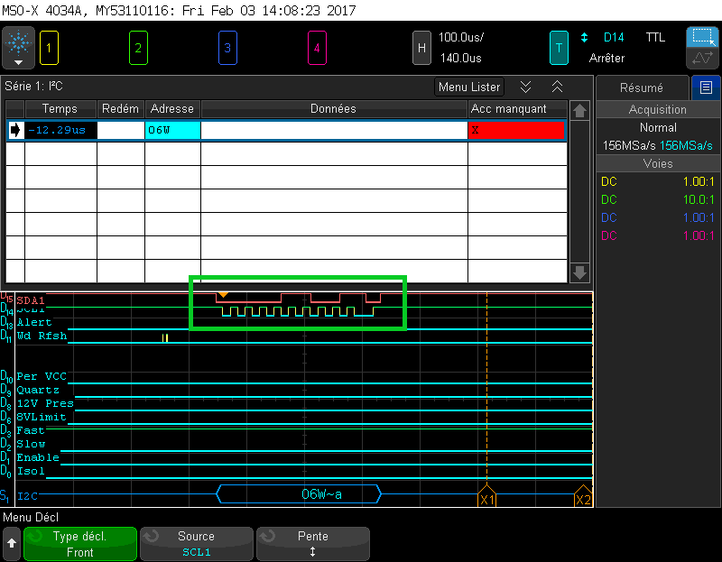
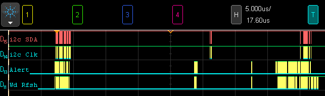
Here is what my oscilloscope sees when I run the sequence.
06 is the content of the TXBUFF, when the slave's address is 0x044 in I2CSA, as confirmed before and after with the debugger.
Obviously the slave doesn't recognize the address and does'nt Ack, so my driver sends a STOP. Then I can reproduce it over and over.

  • Hi Guillaume,

    Thanks for providing the detailed explanation. I haven't seen this issue before and I can't glean much information from the scope shot you've provided without seeing the code that generates it. Can you provide a snippet of the USCI initialization and interrupt code?

    Also, are you seeing this on multiple devices or just the one that experienced the CEM perturbation.

    Best regards,
    Caleb Overbay
  • Here is my init code. As you can see I have mapped structures on the peripheral, but this works well and my driver has worked correctly for months. I kept original names of registers so you will recognize them.

    // INIT PINS
    
       // Set pins to I2C mode
       McuGpio_G_P78Regs_S.Pxysel_U.Bits.Bit13_UW_1Bit = 0b1; // Uart mode
       McuGpio_G_P78Regs_S.Pxysel_U.Bits.Bit14_UW_1Bit = 0b1; // Uart mode
    
       // INIT PERIPHERAL
    
       McuI2c_G_Ucb1Regs_S.Ucbxctl1_S.Ucswrst_UB_1Bit = 0b1; // set Reset (default) before configuration
    
       McuI2c_G_Ucb1Regs_S.Ucbxctl0_S.Ucmodex_UB_2Bit = 0b11; // I2C mode
       McuI2c_G_Ucb1Regs_S.Ucbxctl0_S.Ucsync_UB_1Bit  = 0b1 ; // synchronous mode
    
       McuI2c_G_Ucb1Regs_S.Ucbxctl1_S.Ucsselx_UB_2Bit = 0b10; // select SMCLK as clock source
    
       // SMCLK = 4MHz / 100 = 40kHz
       McuI2c_G_Ucb1Regs_S.Ucbxbr_UW = 100; //SMCLK /x
    
       McuI2c_G_Ucb1Regs_S.Ucbxctl0_S.Ucmst_UB_1Bit    = 0b1;  // i2c Master
    
       McuI2c_G_Ucb1Regs_S.Ucbxctl0_S.Ucmm_UB_1Bit    = 0b0; // UCMM = 0: no multimaster environment
       McuI2c_G_Ucb1Regs_S.Ucbxctl0_S.Ucsla10_UB_1Bit = 0b0; // UCSLA10 = 0: 7bits addressing for slave
       McuI2c_G_Ucb1Regs_S.Ucbxctl0_S.Uca10_UB_1Bit   = 0b0; // UCA10 = 0: 7bits addressing for self
    
       McuI2c_G_Ucb1Regs_S.Ucbxctl1_S.Ucswrst_UB_1Bit = 0b0;  // release reset to start operation

    The driver is not working on interrupts but directly in a blocking sequence with waiting loops.
    Several tranmissions happen between the init and the bug, all fine:


       // Set slave address
       McuI2c_G_Ucb1Regs_S.Ucbxi2Csa_S.I2Csax_UW_10Bit = (G_UWord_t) P_SlaveAddress_UB; // only 7bits addresses are used.
    
       // Set direction to Tx
       McuI2c_G_Ucb1Regs_S.Ucbxctl1_S.Uctr_UB_1Bit = 0b1; // Tx
    
       // send Start
       McuI2c_G_Ucb1Regs_S.Ucbxctl1_S.Uctxstt_UB_1Bit = 1;
    
    //---> this is where I expect the slave address to be sent
    
       // wait end of transmission of Slave Address (Tx Interrupt (nack shouldn't happen here)
       L_ErrorState_E = DrvI2c_P_WaitTxNackFlag_E();
    
       if (L_ErrorState_E == DRVI2C_P_NO_ERROR_E)
       {
       // DATA ADDRESS byte 1
    
          // Start clocking for ack and then sending byte by writing in it TxBuf
          McuI2c_G_Ucb1Regs_S.Ucbxtxbuf_UB = P_DataAddress_UB;
          // TxFlag should rise if ack has been received
          L_ErrorState_E = DrvI2c_P_WaitTxNackFlag_E();
    ....

    The DrvI2c_P_WaitTxNackFlag_E() function waits for either a Tx flag or a NACK flag in a loop:

       while(   (McuI2c_G_Ucb1Regs_S.Ucbxifg_U.Bits.Uctxifg_UB_1Bit   == 0) // TX flag
             && (McuI2c_G_Ucb1Regs_S.Ucbxifg_U.Bits.Ucnackifg_UB_1Bit == 0) // NACK flag
             && (L_Timeout_UW < DRVI2C_P_TIMEOUT_UW)  )
    ...

    I can't test this on several boards, for now I have only one.
    The perturbation is a spike from an over enthousiast relay on a high current line, and I see it on the oscilloscope so the I2C lines sees it. but it is long before the start of the communication try. The bug appears randomly, then I can reapeat it by trying a start again, over and over, until I reset the peripheral with the UCSWRST bit.

    I looks like the peripheral believe it is in the middle of a transmission, except I can't see why it sends a proper Start on the line.
    For now I reset the driver when it happens, but I want to prevent it, which I hope I will be able too when we understand how it happens.

  • Hi Guillaume,

    Your code looks like everything is setup properly and I agree that it seems the device is using the contents of TXBUFF as the slave address. I'd like to see a scope shot of the perturbation on the I2C lines to know what kind of stress the device may be undergoing.

    This isn't a common issue and most likely the perturbation is violating the I2C standard and putting the I2C state machine in some kind of unknown state. I think the best solution is to ensure that the I2C lines don't see that disturbance.

    Best regards,
    Caleb Overbay
  • Hi Caleb,
    Thank you for your answers.

    Here is what the perturbation looks like from the I2C lines (seen as digital on the scope).
    As you can see the pulse ripples quite randomly through all my signals.
    This is obviously not supposed to happen in real conditions, and I don't expect the serial periph to handle it.

    I was just hoping I had missed something and/or this peculiar state would mean anything to you, and it would give me leads to detect it beforehand or prevent it somehow.

    I have not been able to identify status flags that would give an indication on this.

    I"ve managed to work around it partly by reseting the peripheral with the UCSWRST bit in case of error.
    It's just more complicated to manage the failed frame...

    At least it solved the problem I had not knowing how to test my robustness function on the bus :)

  • Hi Guillaume,

    Were you able to isolate the I2C lines and keep the perturbation from affecting the MSP430?

    Best regards,
    Caleb Overbay
  • Hi,

    Yes, we isolated the lines with an aluminium foil around the cables and it works.

    My test bench looks so shiny now  :o)

    I just hope I'll never have to show it to the customer...

**Attention** This is a public forum