Part Number: MSP430F5529
Other Parts Discussed in Thread: PGA116
How to communicate with PGA116 from MSP430f5529 to set the gain of PGA116?
The PGA116 is given DVdd supply from micro controller (3.3V), CS, DOUT, DIN & SCLK from corresponding micro controller pins, ENABLE pin is also kept high connecting to 3.3V.
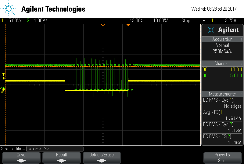
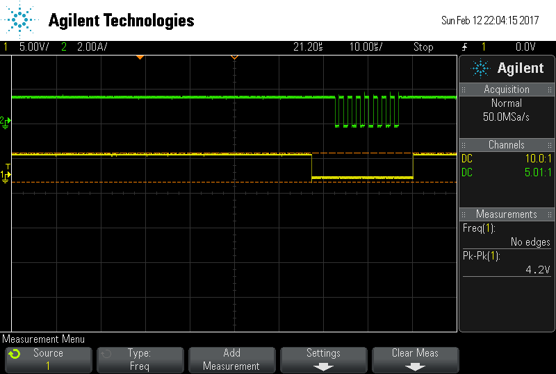
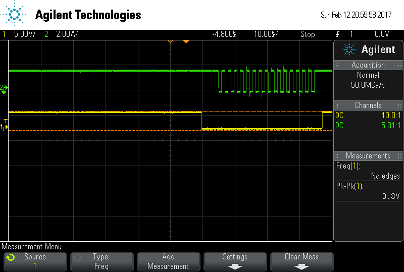
How to send 16 bit data from master out pin of micro controller to DIN pin of PGA116?
How to access registers in PGA116?
Following program is used to initialize SPI clock, transmit and receive data
#include <msp430.h>
unsigned char MST_Data,MST_Data2,SLV_Data;
unsigned char temp;
int main(void)
{
volatile unsigned int i;
WDTCTL = WDTPW+WDTHOLD; // Stop watchdog timer
P4OUT |= 0x02; // Set P1.0 for LED
// Set P1.1 for slave reset
P1DIR |= 0x01; // Set P1.0-2 to output direction
P4DIR |= 0x02;
P3SEL |= BIT3+BIT4; // P3.3,4 option select
P2SEL |= BIT7; // P2.7 option select
UCA0CTL1 |= UCSWRST; // **Put state machine in reset**
UCA0CTL0 |= UCMST+UCSYNC+UCCKPL+UCMSB; // 3-pin, 8-bit SPI master
// Clock polarity high, MSB
UCA0CTL1 |= UCSSEL_2; // SMCLK
UCA0BR0 = 0x02; // /2
UCA0BR1 = 0; //
UCA0MCTL = 0; // No modulation
UCA0CTL1 &= ~UCSWRST; // **Initialize USCI state machine**
UCA0IE |= UCRXIE; // Enable USCI_A0 RX interrupt
P4OUT &= ~0x02; // Now with SPI signals initialized,
P4OUT |= 0x02; // reset slave
for(i=50;i>0;i--); // Wait for slave to initialize
MST_Data = 0x00; // First byte
MST_Data2 = 0xA6;// Second byte
SLV_Data = 0x00; //
while (!(UCA0IFG&UCTXIFG)); // USCI_A0 TX buffer ready?
UCA0TXBUF = MST_Data; // Transmit first character
__bis_SR_register(LPM0_bits + GIE); // CPU off, enable interrupts
}
#if defined(__TI_COMPILER_VERSION__) || defined(__IAR_SYSTEMS_ICC__)
#pragma vector=USCI_A0_VECTOR
__interrupt void USCI_A0_ISR(void)
#elif defined(__GNUC__)
void __attribute__ ((interrupt(USCI_A0_VECTOR))) USCI_A0_ISR (void)
#else
#error Compiler not supported!
#endif
{
volatile unsigned int i;
switch(__even_in_range(UCA0IV,4))
{
case 0: break; // Vector 0 - no interrupt
case 2: // Vector 2 - RXIFG
while (!(UCA0IFG&UCTXIFG)); // USCI_A0 TX buffer ready?
SLV_Data=UCA0RXBUF;
if (UCA0RXBUF==SLV_Data) // Test for correct character RX'd
P1OUT |= 0x01; // If correct, light LED
else
P1OUT &= ~0x01; // If incorrect, clear LED
// MST_Data++; // Increment data
// SLV_Data++;
UCA0TXBUF = MST_Data; // Transmit First byte
while (!(UCA0IFG&UCTXIFG));
UCA0TXBUF = MST_Data2;//Transmit Second byte
while((UCA0STAT&BIT0)); // check transmission over
for(i = 20; i>0; i--); // Add time between transmissions to
// make sure slave can process information
break;
case 4: break; // Vector 4 - TXIFG
default: break;
}
}
I'm new to MSP programming & Thanks in advance