Part Number: MSP430F5438A
Tool/software: Code Composer Studio
Hello,
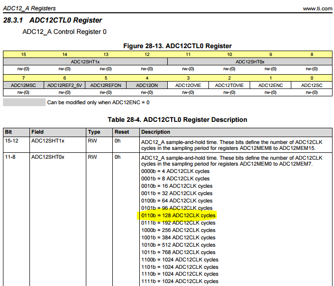
I am very confused with the manner to setup ADC12 sampling time triggered by Timer A. I do not understand how the ADC12SHT0x register works and how this is related with the timer time.
The objective of my code is acquire 5 different signals from 5 ADC channels. The sampling time is 1 ms.
I have different questions on my mind:
1.- Calculating the ADCCLK cycles for 1 kHz, the frequency of ADC12 should be configured at 32768 Hz? with other values I can not obtain a valid value. With this frequency I have 33 CLK cycles.
2.- On this way, do I have to configure the ADC12SHT0x to ADC12SHT0_4(64 cycles)?
3.- Should the timer be configured to count 1 ms too?
4.- On other posts of this forum, I read different ways to program the TA1CCTL0, some people uses the OUTMOD_4 and others OUTMOD_3, Which is the best way to configure it?
I tried to program the configuration of these peripherals in order to the ADC has a 1 ms of sampling time.
Is the code below the suitable way?
//Timer A initialization
void Timer_init (void)
{
	  TA1CCR0 = 33-1;							// Set to 1ms
	  TA1CCR0=0;
	  TA1CTL = TASSEL_1 + MC_1 + TACLR;         // ACLK, upmode, clear TAR
	  TA1CCTL0=OUTMOD_4;
}


// ADC12 Initialization
void ADC12_init (void)
{
	// ADC12 On, S&H 64 cycles, Multiple conversion
	ADC12CTL0=ADC12ON+ADC12SHT0_4+ADC12MSC;

	//Timer A1, SAMPCOM from sampling timer,
	//ADC12CLK=ACLK=32768 Hz and Repeat sequence of channels
	ADC12CTL1=ADC12SHS_1+ADC12SHP+ADC12SSEL_1+ADC12CONSEQ_3;


	ADC12CTL2=ADC12RES_2; //12 bits of resolution (13 cycles)

	ADC12MCTL0 = ADC12INCH_7;                  // Channel = A7
	ADC12MCTL1 = ADC12INCH_12;                 // Channel = A12
	ADC12MCTL2 = ADC12INCH_13;                 // Channel = A13
	ADC12MCTL2 = ADC12INCH_14;                 // Channel = A14
	ADC12MCTL3 = ADC12INCH_15+ADC12EOS;        // Channel = A15, end seq.

	ADC12CTL0|=ADC12ENC;	//Enable conversion
}
Thanks in advance.
Best regards,
Miguel