Tool/software: Code Composer Studio
Hi all,
I've been struggling for the past couple of weeks to get basic I2C working using the MSP430FR5994 and the VEML6070. My code is below.
#include <msp430.h>
#include <stdio.h>

/*
 * Starting I2C with UV sensor.
 */

int MSB;
int LSB;
int test;
long UV_data;
int main(void) {
    WDTCTL = WDTPW | WDTHOLD;	// Stop watchdog timer

    // Configure one FRAM waitstate as required by the device datasheet for MCLK
    // operation beyond 8MHz _before_ configuring the clock system.
    FRCTL0 = FRCTLPW | NWAITS_1; // Change the NACCESS_x value to add the right amount of waitstates (1 per datasheet)

    // Set up XT1, 32.768 kHz external crystal
    PJSEL0 = BIT4 | BIT5;                   // For XT1

    // Disable the GPIO power-on default high-impedance mode to activate
    // previously configured port settings
    PM5CTL0 &= ~LOCKLPM5;

    // Clock System Setup
    CSCTL0_H = CSKEY_H;                     // Unlock CS registers
    CSCTL1 = DCOFSEL_0;                     // Set DCO to 1MHz
    // Set SMCLK = MCLK = DCO, ACLK = VLOCLK
    CSCTL2 = SELA__LFXTCLK | SELS__DCOCLK | SELM__DCOCLK;
    // Per Device Errata set divider to 4 before changing frequency to
    // prevent out of spec operation from overshoot transient
    CSCTL3 = DIVA__4 | DIVS__4 | DIVM__4;   // Set all corresponding clk sources to divide by 4 for errata
    CSCTL1 = DCOFSEL_4 | DCORSEL;           // Set DCO to 16MHz
    // Delay by ~10us to let DCO settle. 60 cycles = 20 cycles buffer + (10us / (1/4MHz))
    __delay_cycles(60);
    CSCTL3 = DIVA__32 | DIVS__1 | DIVM__1;   // Clock dividers (divide max clock by these)
    CSCTL4 &= ~LFXTOFF;
        do
        {
            CSCTL5 &= ~LFXTOFFG;                // Clear XT1 fault flag
            SFRIFG1 &= ~OFIFG;
        } while (SFRIFG1 & OFIFG);              // Test oscillator fault flag
    CSCTL0_H = 0;                           // Lock CS registers

    // Configure USCI_B1 for I2C mode, transmitter
	UCB1CTLW0 |= UCSWRST;                   // Software reset enabled
	UCB1CTLW0 |= UCMODE_3 | UCMST | UCSYNC | UCSSEL__SMCLK; // I2C mode, Master mode, sync, UCTR = 0, SMCLK
	UCB1CTLW1 |= UCASTP_2;                  // Stop is auto generated

    // Set up UCB1 (SDA and SCL function, per datasheet)
	P5DIR &= ~(BIT0 | BIT1);
	P5REN &= ~(BIT0 | BIT1);
    P5SEL1 &= ~(BIT0 | BIT1);
    P5SEL0 = BIT0 | BIT1;
											// after UCB1TBCNT is reached
	UCB1BRW = UCBR9;                       // baudrate = SMCLK / (0x0200h = 512 decimal)
	UCB1TBCNT = 0x0001;                     // number of bytes to be received (5)
	UCB1I2CSA = 0x18;                     // Initialization address
	UCB1CTLW0 &= ~UCSWRST;
	UCB1IE |= UCNACKIE | UCTXIFG0 | UCRXIFG0;
	//UCB1CTLW0 |= UCTXSTT;
	//__bis_SR_register(LPM3_bits | GIE);

	//test = 10;
	//UCB1CTLW0 |=

	while(1) {
		UCB1CTLW0 |= UCSWRST; // Change registers for LSB
		UCB1I2CSA = 0x39; // Slave address, read MSB (39h)
		UCB1CTLW0 &= ~UCSWRST; // Stop changing registers
		UCB1IE |= UCNACKIE | UCTXIFG0 | UCRXIFG0;
		test = 1; // get MSB
		UCB1CTLW0 |= UCTXSTT; // Start command
		__bis_SR_register(LPM3_bits | GIE);

		UCB1CTLW0 |= UCSWRST; // Change registers for LSB
		UCB1I2CSA = 0x38; // Slave address, read LSB (38h)
		UCB1CTL1 &= ~UCSWRST; // Stop changing registers
		UCB1IE |= UCNACKIE | UCTXIFG0 | UCRXIFG0;
		test = 0;
		UCB1CTLW0 |= UCTXSTT; // Start command
		__bis_SR_register(LPM3_bits | GIE);
		printf("%d\n", MSB);
		printf("%d\n", LSB);
		UV_data = (MSB << 8) | LSB;
		printf("%ld\n", UV_data);
		__delay_cycles(16000000);
	}
}

#if defined(__TI_COMPILER_VERSION__) || defined(__IAR_SYSTEMS_ICC__)
#pragma vector = EUSCI_B1_VECTOR
__interrupt void USCI_B1_ISR(void)
#elif defined(__GNUC__)
void __attribute__ ((interrupt(EUSCI_B1_VECTOR))) USCI_B1_ISR (void)
#else
#error Compiler not supported!
#endif
{
    switch(__even_in_range(UCB1IV, USCI_I2C_UCBIT9IFG))
    {
        case USCI_NONE:          break;     // Vector 0: No interrupts
        case USCI_I2C_UCALIFG:   break;     // Vector 2: ALIFG
        case USCI_I2C_UCNACKIFG:            // Vector 4: NACKIFG
            UCB1CTL1 |= UCTXSTT;            // I2C start condition
            break;
        case USCI_I2C_UCSTTIFG:  break;     // Vector 6: STTIFG
        case USCI_I2C_UCSTPIFG:  break;     // Vector 8: STPIFG
        case USCI_I2C_UCRXIFG3:  break;     // Vector 10: RXIFG3
        case USCI_I2C_UCTXIFG3:  break;     // Vector 12: TXIFG3
        case USCI_I2C_UCRXIFG2:  break;     // Vector 14: RXIFG2
        case USCI_I2C_UCTXIFG2:  break;     // Vector 16: TXIFG2
        case USCI_I2C_UCRXIFG1:  break;     // Vector 18: RXIFG1
        case USCI_I2C_UCTXIFG1:  break;     // Vector 20: TXIFG1
        case USCI_I2C_UCRXIFG0:             // Vector 22: RXIFG0
        	if (test==1){
        		MSB = UCB1RXBUF; // Get MSB data
        	}
        	else if (test==0) {
        		LSB = UCB1RXBUF; // Get LSB
        	}
        	__bic_SR_register_on_exit(LPM3_bits);
            break;
        case USCI_I2C_UCTXIFG0:  	        // Vector 24: TXIFG0
        	//UCB1TXBUF = 0xE; // 00001110, longest integration time and ACK off, shut down off
        	__bic_SR_register_on_exit(LPM3_bits);
        	break;
        case USCI_I2C_UCBCNTIFG:            // Vector 26: BCNTIFG
            P1OUT ^= BIT0;                  // Toggle LED on P1.0
            break;
        case USCI_I2C_UCCLTOIFG: break;     // Vector 28: clock low timeout
        case USCI_I2C_UCBIT9IFG: break;     // Vector 30: 9th bit
        default: break;
    }
}
For now, ignore the 0x18 address. According to the VEML6070 datasheet, this is an address that should be read for initialization purposes, but any attempt I make to read it results in a NACK.
The other two addresses, 0x39 and 0x38, are read-only registers according to the datasheet of the VEML6070, and provide UV data in MSB, LSB format.
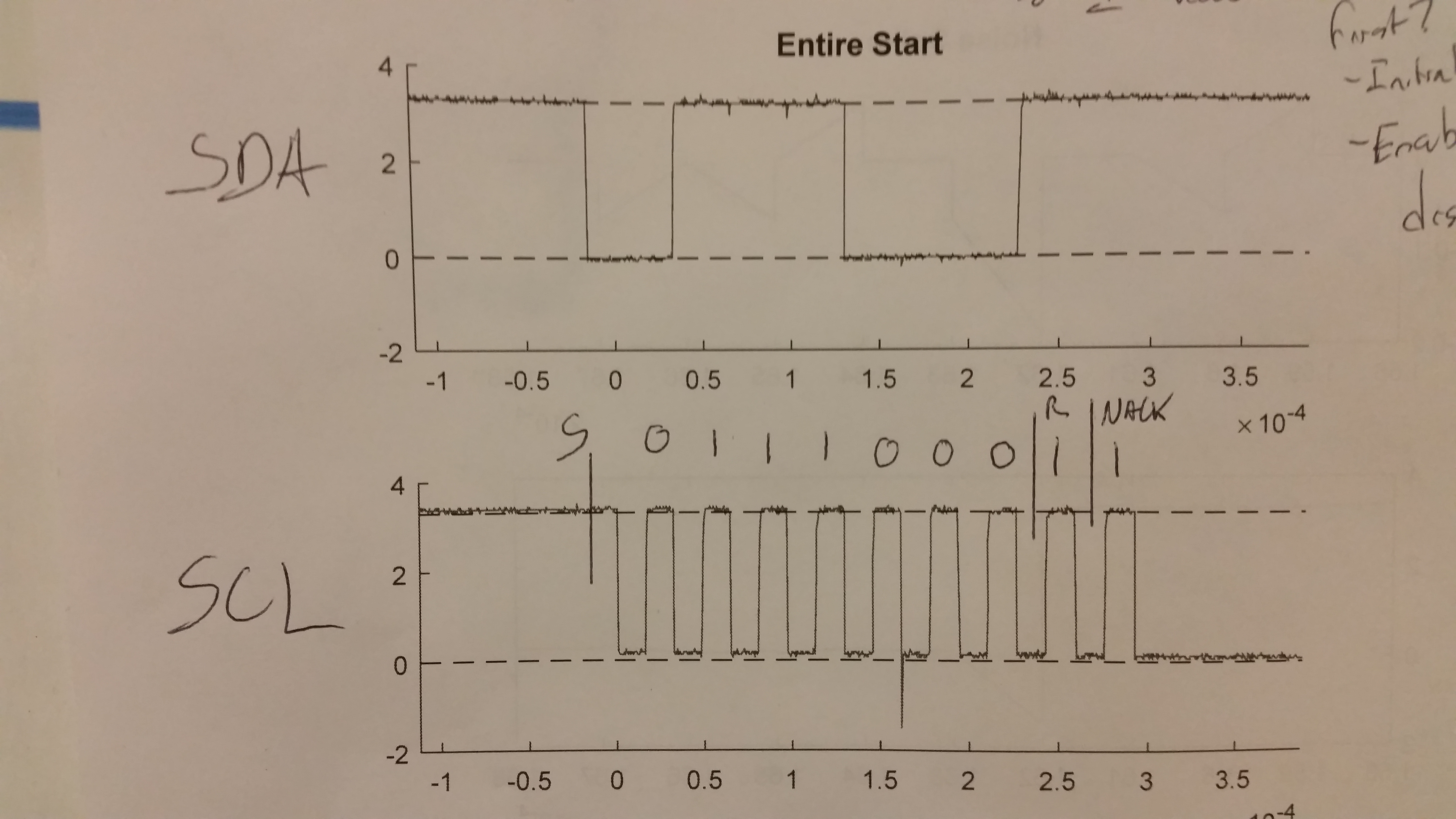
The response of the MSP to this code is the following:

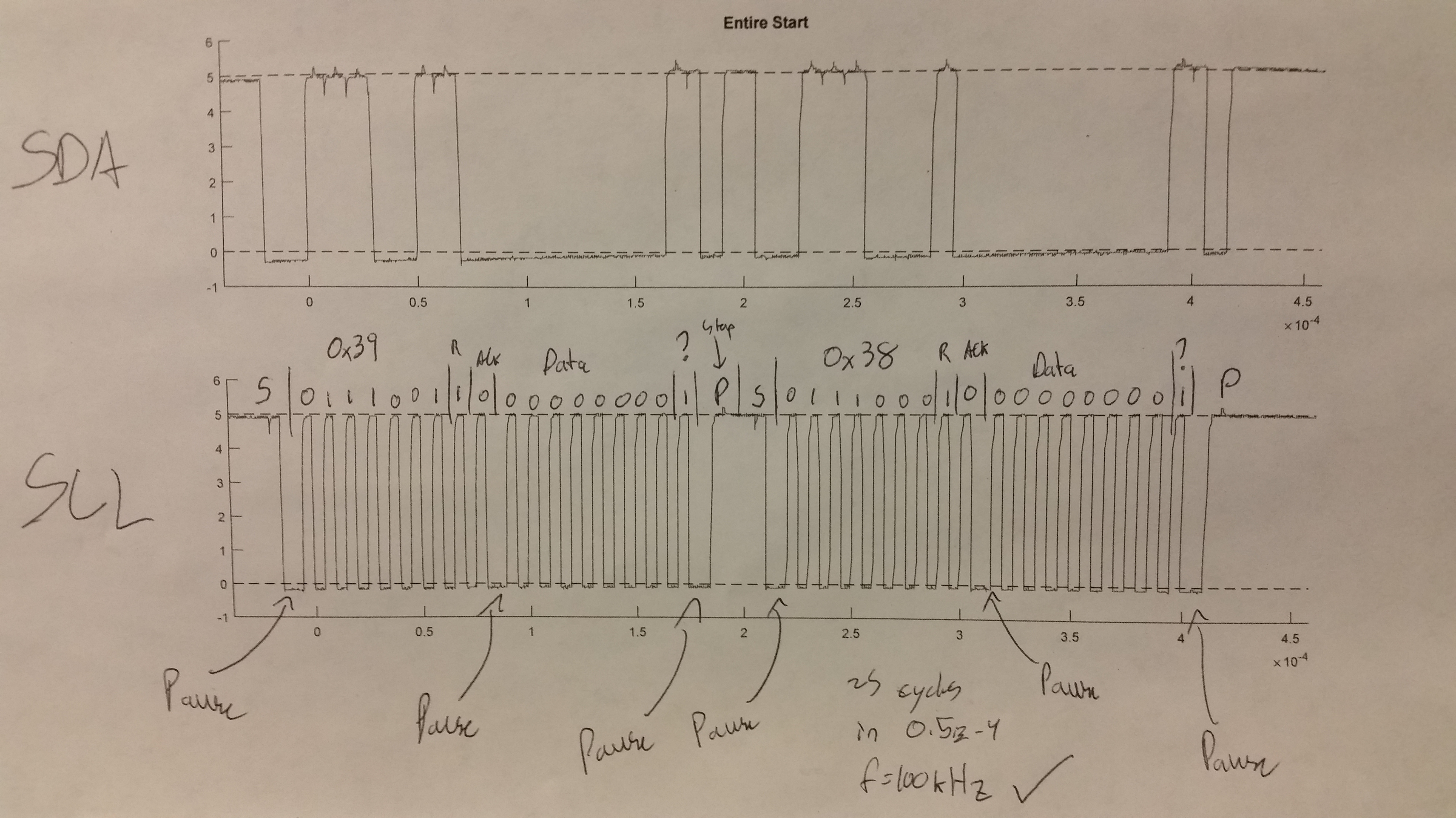
The response of an Arduino polling the same addresses is the following:

Upon sending the 0x38 address, the Arduino receives an ACK while the MSP430 receives a NACK.
Here are my thoughts on this:
- Why does the Arduino appear to pause for a cycle periodically?
- Do I have to operate at 100kHz as the Arduino is? I am currently operating at closer to 32kHz because I thought this would increase my chances of success.
- Can I change the mode of the MSP430FR5994 from standard to fast and vice versa? I didn't see anything about changing the mode in the user's guide, so I assume that the mode is only a number and no change in code need be made.
- Both the MSP430FR5994 and the VEML6070 can operate on 3.3V logic. With that in mind, the fact that the Arduino uses 5V logic should make no difference, right?
- Could the voltage spike be a problem in the MSP plot? If so, how do I deal with that?
- I don't see a stop set in the MSP plot; is that due to the fact that I got a NACK?
- Based on the datasheet of the VEML6070, I don't think that I need to initialize the device to access data registers. Would you agree?
- I don't see the master (Arduino) sending an ACK to the VEML6070, which the VEML6070's datasheet says should happen. This doesn't appear to be a problem.
- Can the master receiver ACK be enabled and disabled?
- Does anything look bad about my MSP I2C signal versus the Arduino signal?
A member of my group is similarly having trouble integrating SPI with the MSP430. We're using the breakout for the VEML6070, which appears to use 10k resistors instead of the 2.2k recommended in the VEML6070 datasheet. I've tried a resistive divider to bring down the value of the pullup resistors, but that doesn't appear to work.
When running code, I've made sure that all registers are using the correct values as much as possible. I've check pin configuration, clock speed, and eUSCI_B1 configuration extensively.
My test setup is as pictured below.

Yellow goes to ground, blue to P5.1, and green to P5.0. I recognize that this isn't the best setup, but wires of the exact same length and the same pullup resistors work for the Arduino.
For reference, the Arduino is a SparkFun RedBoard.
Basically, I need help getting an ACK from the slave VEML6070 using I2C. I've tried so much, but can't seem to get a positive result.
Any help is greatly appreciated!