This thread has been locked.

If you have a related question, please click the "Ask a related question" button in the top right corner. The newly created question will be automatically linked to this question.

MSP430I2041: MSP430FR2041 CONTROLLER RESET

Part Number: MSP430I2041


HELLO

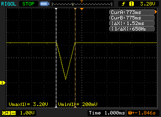
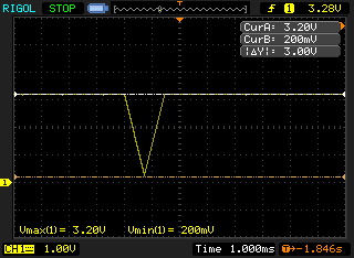
I HAVE IMPLEMENTED MY DESIGN WITH MSP430I2041-VQFN CONTROLLER. DURING TESTING I HAVE FACED PROBLEM OF CONTROLLER RESET WHENEVER OPERATING RELAY ON GPIO PIN. I HAVE CHANGED RC TIME CONSTANT VALUES AS BELOW.

R: 10K FROM 47K

C: 1nF FROM 2.2nF

AFTER CHANGING RC CONSTANT VALUES THE PROBLEM OF CONTROLLER RESET IS SOLVED UP TO SOME EXTENT.

CAN ANYONE GIVE OTHER SUGGESTION ON THIS ISSUE.

  • Hello dipesh,

    Is the RST trace closely coupled with the GPIO line? Did you experience any issues when prototyping with a TI-designed EVM? Can you please provide a schematic, board layout image, and oscilloscope screenshots of the RST and GPIO lines in question? It is import that the RST line stay steady at VCC to avoid unwanted resets. The new RC setup works better because it includes a stronger pull to VCC, indicating that some other component of your design is influencing the RST line.

    Regards,
    Ryan
  • Hello Ryan,

    As you said I have checked in layout the RST trace is not coupled with GPIO line. There is enough space between these two traces. I am attaching oscilloscope screenshot of RST line. Further which type of component can cause this type of issue.

  • Can you also include GPIO pin and Vcc rail screenshots? Is the relay affecting the power supply to the MSP430? Make sure that VCORE capacitance is 470 nF and that the decoupling capacitance at VCC is greater than 4.7 uF (10 uF + 100 nF recommended).

    Regards,
    Ryan
  • HELLO RYAN


    I HAVE GONE THROUGH ALL THE COMPONENTS VALUE AS YOU MENTIONED. I HAVE USED SAME VALUE CAPACITORS & DECOUPLING CAPACITOR VALUE IS 100uF/50V. ALSO AT THE TIME OF CONTROLLER RESET THERE IS NO ANY KIND OF FLUCTUATION ON GPIO AS WELL AS SUPPLY PIN. WAVEFORM ARE CONSTANT. ONE THING I WANT TO ASK YOU THAT WHAT HAPPEN IF I WILL CHANGE VALUE OF RESISTOR ON RC TIME CONSTANT TO 4.7K OR ANY OTHER LOW VALUE. IS THERE ANY RULE RELATED TO VALUE OF RESISTOR ON RC NETWORK ? IF YES CAN YOU PLEASE EXPLAIN IT.

  • Hi dipesh,

    The 47 kOhm recommended resistance is primarily for SBW communication, if you reduce this value too far then the RST may not be able to communicate properly through 2-wire JTAG. Does your program always reset while performing a specific part of code, and is there a possibility that this firmware which might cause a software RST?

    Regards,
    Ryan

**Attention** This is a public forum