


Other Parts Discussed in Thread: MSP-FET, MSP-GANG
When designing my board, I noticed that the MSP-FET had an option for a backchannel UART. Hoping to use this serial interface to debug my firmware, I connected my processor's UART pins to the corresponding pins on the programming header. What I'm hoping to do is implement a printf debugging setup on my part and see the output in a serial terminal on my computer.
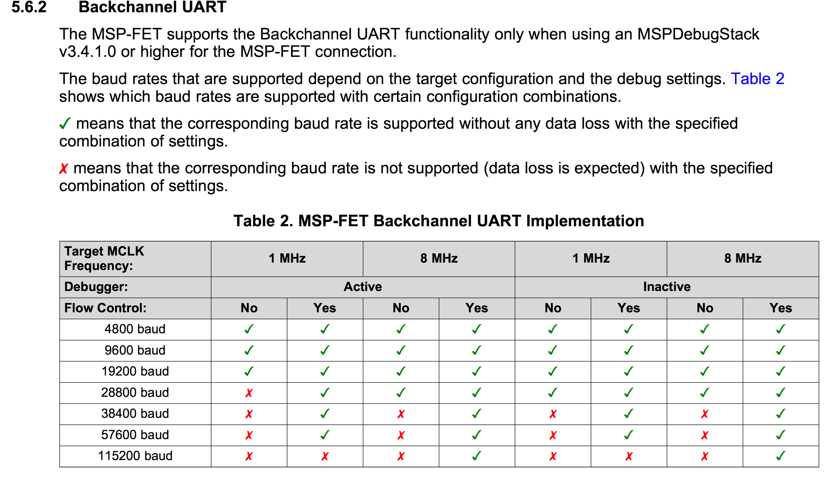
I found the following table in the MSP Debuggers Guide (www.ti.com/.../slau647f.pdf).
Is this table indicating that I need to send some command down to the MSP-FET in order to initialize the UART?
So far, I have the UART on my part set to 1200 baud (which may be a problem), and I send out a string every 2 seconds. I can see the data on the pins, but nothing appears in my serial terminal.
I am working on a Mac using the "Serial" App from the App Store (itunes.apple.com/.../id877615577. When I open the application, I have the choice of two unique TI "COM ports".

From what I've been able to determine so far, selecting Port 2 causes the MSP-FET to crash in CSS7, so I'm assuming I need to select Port 1.
Any suggestions would be much appreciated,
Trigg


