This thread has been locked.

If you have a related question, please click the "Ask a related question" button in the top right corner. The newly created question will be automatically linked to this question.

MSP432P401R: Polling data for 3 seconds using a timer

Part Number: MSP432P401R
Other Parts Discussed in Thread: ENERGIA

I am following the instructions on how to calibrate the 2 clocks of a sensor. I am stuck on the step where I need to poll data from the sensor's FIFO data register using I2C for exactly 3 seconds. I know the best way to go about doing this is by using one of the MSP432's timer, but I do not have enough experience to implement this. Any suggestions would be greatly appreciated!

  • Hello,

    I would like to help you with this but first I'd like to ask some clarifying question.  I assume from your statement that your sensor uses I2C communication to receive some sort of calibration data.  I am not familiar with applications that require the communication to occur for any exact length of time as you suggest.  Can you give me more information about the sensor you are using? 

  • I would do something similar to the Energia/Arduino millis() facility. Set up Systick for a 1ms (If that provides good enough precision) interrupt and in the ISR, increment a 32 bit unsigned variable. This is good if you need this kind of timing functionality elsewhere in your program.

    In your I2C send data routine, take note of the variable at the start of the data stream and stop when the timer increases by 3000.

    Or, set a timer for a 3 second interrupt and have its ISR set a flag, just start the timer at the start of your data sending and constantly poll the flag.
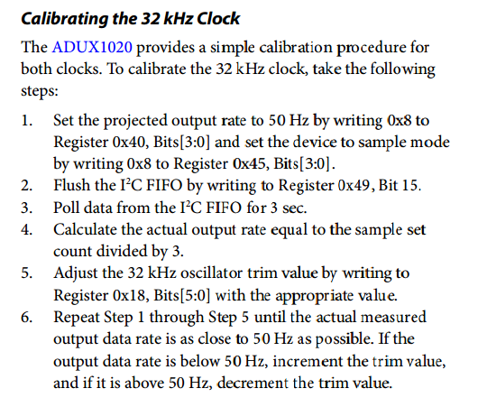
  • Of course, the part that I'm using is an ADI sensor called ADUX1020. I need to calibrate the clock (32kHz) that sets the sample timing and internet power state machine, as well as another internal clock (32MHz) that controls the timing of data capture. Heres the instructions to calibrate the 32kHz clock from the part's datasheet. I am on step 3. 

  • Since you have to poll it, either of my suggestions would work.
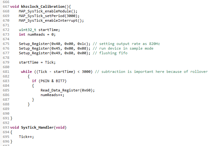
  • Yes, the problem I have is that I do not have any experience using timers so I don't know how to implement it. The following is my current code.

    /* DriverLib Defines */
    #include "driverlib.h"
    #include <stdint.h>
    #include <stdbool.h>
    #include <string.h>
    #include <stdio.h>
    
    /* Slave Address for I2C Slave */
    #define SLAVE_ADDRESS       0x64
    #define NUM_OF_REC_BYTES    2
    
    //static uint8_t Read;
    static uint8_t RX;
    static uint8_t TXByteCtr;
    //static float horAngle, verAngle, intensity;
    static uint16_t X1, X2, Y1, Y2;
    
    /* Variables */
    static uint8_t TXData[3] = {0x12, 0x5f, 0x0c};
    static uint8_t RXData[NUM_OF_REC_BYTES];
    static volatile uint32_t xferIndex;
    static volatile bool stopSent;


    /* I2C Master Configuration Parameter */
    const eUSCI_I2C_MasterConfig i2cConfig =
    {
            EUSCI_B_I2C_CLOCKSOURCE_SMCLK,          // SMCLK Clock Source
            3000000,                                // SMCLK = 3MHz
            EUSCI_B_I2C_SET_DATA_RATE_100KBPS,      // Desired I2C Clock of 100khz
            0,                                      // No byte counter threshold
            EUSCI_B_I2C_NO_AUTO_STOP                // No Autostop
    };
    
    #define TIMER_PERIOD    0xB71B
    
    /* Timer_A UpMode Configuration Parameter */
    const Timer_A_UpModeConfig upConfig =
    {
            TIMER_A_CLOCKSOURCE_SMCLK,              // SMCLK Clock Source
            TIMER_A_CLOCKSOURCE_DIVIDER_64,          // SMCLK/1 = 3MHz
            TIMER_PERIOD,                           // 5000 tick period
            TIMER_A_TAIE_INTERRUPT_DISABLE,         // Disable Timer interrupt
            TIMER_A_CCIE_CCR0_INTERRUPT_ENABLE ,    // Enable CCR0 interrupt
            TIMER_A_DO_CLEAR                        // Clear value
    };
    
    // UART Configuration
    const eUSCI_UART_Config uartConfig =
    {
            EUSCI_A_UART_CLOCKSOURCE_SMCLK,          // SMCLK Clock Source
    
    		//19200
    		39,
    		1,
    		0,


            EUSCI_A_UART_NO_PARITY,                  // No Parity
            EUSCI_A_UART_LSB_FIRST,                  // LSB First
            EUSCI_A_UART_ONE_STOP_BIT,               // One stop bit
            EUSCI_A_UART_MODE,                       // UART mode
            EUSCI_A_UART_OVERSAMPLING_BAUDRATE_GENERATION  // Oversampling
    };
    
    
    bool Setup_Register(unsigned char, unsigned char, unsigned char);
    uint16_t Read_Data_Register(unsigned char);
    
    void khzclock_Calibration();
    void Setup_Config();
    void UART_Transmit(uint16_t);
    void ADC_Calibration();
    
    
    const uint32_t default_config[] = {
            0x000c000f,
            0x00101010,
            0x0011004c,
            0x00125f0c,
            0x0013ada5,
            0x00140080,
            0x00150000,
            0x00160600,
            0x00170000,
            0x00182693,
            0x00190004,
            0x001a4280,
            0x001b0060,
            0x001c2094, // SDA/SCL pad slew rate limiter enabled
                        // INT output: enabled
                        // INT input: disabled
            0x001d0000,
            0x001e0001,
            0x001f0000,
            0x00200320,
            0x00210513,
            0x00220320,
            0x00230113,
            0x00240000,
            0x00252414,
            0x00262414,
            0x00270022,
            0x00280000,
            0x00290300,
            0x002a1770,
            0x002b157c,
            0x002c4268,
            0x002d2710,
            0x002e0000,
            0x002f0000,
            0x00300000,
            0x00310000,
            0x00320040,
            0x00330000,
            0x0034E400,
            0x00388080,
            0x00398080,
    
            // Initial values
            0x003a1e00,
            0x003b1e00,
            0x003c1e00,
            0x003d1e00,
    
            0x003e0000,
            0x0040806d,
            0x00411f2f,
            0x00424000,
            0x00430000,
            0x00440005,
            //0x00460020, // Decimation rate for sample mode: 4
            0x00460030,
    		0x004800df, // INT_STATUS register: sample interrupt
            0x00490000,
            0x00450008, // Operation Mode: Sample Mode
    };
    
    int main(void)
    
    {
        /* Disabling the Watchdog  */
        MAP_WDT_A_holdTimer();
    
        /* Setting DCO to 12MHz */
        CS_setDCOCenteredFrequency(CS_DCO_FREQUENCY_12);
    
        /* Setting DCO to 24MHz (upping Vcore)
        FlashCtl_setWaitState(FLASH_BANK0, 2);
        FlashCtl_setWaitState(FLASH_BANK1, 2);
        MAP_PCM_setCoreVoltageLevel(PCM_VCORE1);
        CS_setDCOCenteredFrequency(CS_DCO_FREQUENCY_24);
        */
    
        /* Select Port 1 for I2C - Set Pin 6, 7 to input Primary Module Function,
         *   (UCB0SIMO/UCB0SDA, UCB0SOMI/UCB0SCL).
         */
    
        MAP_GPIO_setAsPeripheralModuleFunctionInputPin(GPIO_PORT_P1,
                GPIO_PIN6 + GPIO_PIN7, GPIO_PRIMARY_MODULE_FUNCTION);
    
        /* Selecting P1.2 and P1.3 in UART mode */
        MAP_GPIO_setAsPeripheralModuleFunctionInputPin(GPIO_PORT_P1,
                GPIO_PIN1 | GPIO_PIN2 | GPIO_PIN3, GPIO_PRIMARY_MODULE_FUNCTION);
    
        stopSent = false;
        memset(RXData, 0x00, NUM_OF_REC_BYTES);
    
        /* Initializing I2C Master to SMCLK at 100khz with no autostop */
        MAP_I2C_initMaster(EUSCI_B0_BASE, &i2cConfig);
    
        /* Specify slave address */
        MAP_I2C_setSlaveAddress(EUSCI_B0_BASE, SLAVE_ADDRESS);
    
        /* Set Master in transmit mode */
        MAP_I2C_setMode(EUSCI_B0_BASE, EUSCI_B_I2C_TRANSMIT_MODE);
    
        /* Enable I2C Module to start operations */
        MAP_I2C_enableModule(EUSCI_B0_BASE);
    
        /* Configuring UART Module */
        MAP_UART_initModule(EUSCI_A0_BASE, &uartConfig);
    
        /* Enable UART module */
        MAP_UART_enableModule(EUSCI_A0_BASE);
    
        /* Enable and clear the interrupt flag */
        MAP_I2C_clearInterruptFlag(EUSCI_B0_BASE,
                EUSCI_B_I2C_TRANSMIT_INTERRUPT0 + EUSCI_B_I2C_RECEIVE_INTERRUPT0);
    
        //Enable master Receive interrupt
        MAP_I2C_enableInterrupt(EUSCI_B0_BASE, EUSCI_B_I2C_TRANSMIT_INTERRUPT0);
        MAP_Interrupt_enableSleepOnIsrExit();
        MAP_Interrupt_enableInterrupt(INT_EUSCIB0);
    
    
        //MAP_Interrupt_enableSleepOnIsrExit();
        MAP_Timer_A_configureUpMode(TIMER_A1_BASE, &upConfig);
        MAP_Interrupt_enableInterrupt(INT_TA1_0);
    
        MAP_Interrupt_enableMaster();
    
        // set interrupt pin as input
        MAP_GPIO_setAsInputPin(GPIO_PORT_P6, GPIO_PIN7);
    
        printf("reading chip id and version value\n");
        Read_Data_Register(0x08);
    
        printf("setting up registers\n");
        Setup_Register(0x0f, 0x00, 0x01);       // Resetting the device
        Setup_Config();                         //004 Configuration
    
        printf("default config loaded\n");
    
        //printf("calibrating 32 khzclock\n");
        //khzclock_Calibration();
    
        // Setup_Register(0x3A, 0x20, 0x70);
        // Setup_Register(0x3B, 0x1D, 0x50);
        // Setup_Register(0x3C, 0x, 0x);
        // Setup_Register(0x3D, 0x, 0x);


        /*
        MAP_GPIO_clearInterruptFlag(GPIO_PORT_P2, GPIO_PIN7);
        MAP_GPIO_enableInterrupt(GPIO_PORT_P2, GPIO_PIN7);
        MAP_Interrupt_enableInterrupt(INT_PORT2);*/
    
        Setup_Register(0x49, 0x08, 0x20);
        //ADC_Calibration();
        //Setup_Register(0x49, 0x08, 0x20);
    
        while (1)
        {
    
        	if (P6IN & BIT7) {
    
        	//if (data_available == 1) {
        			   Setup_Register(0x49, 0x08, 0x20);
    
        		 	 	X1 = Read_Data_Register(0x00);
        		        X2 = Read_Data_Register(0x01);
        		        Y1 = Read_Data_Register(0x02);
        		        Y2 = Read_Data_Register(0x03);
    
        		       MAP_UART_transmitData(EUSCI_A0_BASE, 0x0a);
        		       UART_Transmit(X1);
        		       UART_Transmit(X2);
        		       UART_Transmit(Y1);
        		       UART_Transmit(Y2);


        		      // data_available = 0;
        	}
    
    
        }
    }
    
    /*******************************************************************************
     * eUSCIB0 ISR. The repeated start and transmit/receive operations happen
     * within this ISR.
     *******************************************************************************/
    void EUSCIB0_IRQHandler(void)
    {
        uint_fast16_t status;
    
        status = MAP_I2C_getEnabledInterruptStatus(EUSCI_B0_BASE);
        MAP_I2C_clearInterruptFlag(EUSCI_B0_BASE, status);
    
        /* If we reached the transmit interrupt, it means we are at index 1 of
         * the transmit buffer. When doing a repeated start, before we reach the
         * last byte we will need to change the mode to receive mode, set the start
         * condition send bit, and then load the final byte into the TXBUF.
         */
        if (status & EUSCI_B_I2C_TRANSMIT_INTERRUPT0)
        {
            /*if (RX == 0) {*/
                if (TXByteCtr) {
                    //Send the next data and decrement the byte counter
                    MAP_I2C_masterSendMultiByteNext(EUSCI_B0_BASE, TXData[3 - TXByteCtr]);
                    TXByteCtr--;
                }
                else {
                    if (RX == 0) {
                        MAP_I2C_masterSendMultiByteStop(EUSCI_B0_BASE);
                        stopSent = true;
                        MAP_Interrupt_disableSleepOnIsrExit();
                    }
                    else {
                        MAP_I2C_disableInterrupt(EUSCI_B0_BASE, EUSCI_B_I2C_TRANSMIT_INTERRUPT0);
                        MAP_I2C_setMode(EUSCI_B0_BASE, EUSCI_B_I2C_RECEIVE_MODE);
                        xferIndex = 0;
                        MAP_I2C_masterReceiveStart(EUSCI_B0_BASE);
                        MAP_I2C_enableInterrupt(EUSCI_B0_BASE, EUSCI_B_I2C_RECEIVE_INTERRUPT0);
                    }
                }
        }
    
        /* Receives bytes into the receive buffer. If we have received all bytes,
         * send a STOP condition */
        if (status & EUSCI_B_I2C_RECEIVE_INTERRUPT0)
        {
            if(xferIndex == NUM_OF_REC_BYTES - 2)
            {
                MAP_I2C_masterReceiveMultiByteStop(EUSCI_B0_BASE);
                RXData[xferIndex++] = MAP_I2C_masterReceiveMultiByteNext(EUSCI_B0_BASE);
            }
            else if(xferIndex == NUM_OF_REC_BYTES - 1)
            {
                RXData[xferIndex++] = MAP_I2C_masterReceiveMultiByteNext(EUSCI_B0_BASE);
                MAP_I2C_disableInterrupt(EUSCI_B0_BASE, EUSCI_B_I2C_RECEIVE_INTERRUPT0);
                MAP_I2C_setMode(EUSCI_B0_BASE, EUSCI_B_I2C_TRANSMIT_MODE);
                xferIndex = 0;
                stopSent = true;
                MAP_Interrupt_disableSleepOnIsrExit();
            }
            else
            {
                RXData[xferIndex++] = MAP_I2C_masterReceiveMultiByteNext(EUSCI_B0_BASE);
            }
    
        }
    }
    
    /*
    void khzclock_Calibration(){
    
    	Setup_Register(0x40, 0x00, 0x08); // setting output rate as 50Hz
    	Setup_Register(0x45, 0x00, 0x08); // run device in sample mode
    
    	Read_Data_Register(0x00);
    	Read_Data_Register(0x01);
    	Read_Data_Register(0x02);
    	Read_Data_Register(0x03);
    
    	static int count = 0;
    
    	uint8_t j;
    	for(j = 0; j<500; j++)
    	{
    		Read_Data_Register(0x00);
    		Read_Data_Register(0x01);
    		Read_Data_Register(0x02);
    		Read_Data_Register(0x03);
    		count++;
    	}
    
    }
    */
    
    void Setup_Config() {
    
        uint8_t i;
        for (i = 0; i < 54; i++) {
            unsigned char address = (unsigned char)(default_config[i] >> 16);
            unsigned char msb = (unsigned char)(default_config[i] >> 8);
            unsigned char lsb = (unsigned char)(default_config[i]);
    
    
            while (Setup_Register(address, msb, lsb) != 1);
        }
    
    }
    
    void UART_Transmit(uint16_t data) {
    
           unsigned char *ptr = (unsigned char*) &data;
    
           MAP_UART_transmitData(EUSCI_A0_BASE, *ptr++);
           MAP_UART_transmitData(EUSCI_A0_BASE, *ptr);
    
    
    }
    
    void ADC_Calibration() {
    
    	printf("calibrating X1\n");
    
    		uint16_t offset = 0x1e00;
    
    	    	//if (data_available == 1) {
    
    				do {
    
    					if (P6IN & BIT7) {
    	    			   Setup_Register(0x49, 0x08, 0x20);
    	    		       Setup_Register(0x32, 0x0f, 0x4f);
    
    	    		       X1 = Read_Data_Register(0x00);
    
    	    		       offset += 1;
    	    		       Setup_Register(0x3a, (unsigned char)(offset >> 8), (unsigned char)(offset));
    
    	    		       Setup_Register(0x32, 0x00, 0x40);
    					}
    
    				} while (X1 > 3000);


    	printf("final offset: %X\n", offset);
    
    }
    
    bool Setup_Register(unsigned char address, unsigned char highByte, unsigned char lowByte){
    
        while (MAP_I2C_masterIsStopSent(EUSCI_B0_BASE) == EUSCI_B_I2C_SENDING_STOP);
    
        RX = 0;
        TXByteCtr = 2;
    
        TXData[0] = address;
        TXData[1] = highByte;
        TXData[2] = lowByte;
    
        MAP_I2C_disableInterrupt(EUSCI_B0_BASE, EUSCI_B_I2C_RECEIVE_INTERRUPT0);
        MAP_I2C_masterSendMultiByteStart(EUSCI_B0_BASE, TXData[0]);
        MAP_I2C_enableInterrupt(EUSCI_B0_BASE, EUSCI_B_I2C_TRANSMIT_INTERRUPT0);
    
    
        while(!stopSent)
        {
            MAP_PCM_gotoLPM0InterruptSafe();
        }
    
        stopSent = false;
    
        if (address == 0x49)
                return 1;
    
        uint16_t data = Read_Data_Register(address);
    
    
        return (data == (highByte << 8)+lowByte);
    }
    
    uint16_t Read_Data_Register(unsigned char address) {
    
        while (MAP_I2C_masterIsStopSent(EUSCI_B0_BASE) == EUSCI_B_I2C_SENDING_STOP);
    
        RX = 1;
        TXByteCtr = 0;
    
        MAP_I2C_disableInterrupt(EUSCI_B0_BASE, EUSCI_B_I2C_RECEIVE_INTERRUPT0);
        MAP_I2C_masterSendMultiByteStart(EUSCI_B0_BASE, address);
        MAP_I2C_enableInterrupt(EUSCI_B0_BASE, EUSCI_B_I2C_TRANSMIT_INTERRUPT0);
    
    
        while(!stopSent)
        {
            MAP_PCM_gotoLPM0InterruptSafe();
        }
    
        stopSent = false;
    
        return (RXData[0] << 8)+RXData[1];
    }


  • /* Ti copyright boilerplate snipped */
    /*******************************************************************************
     * MSP432 SysTick - Blink LED Program
     *
     * Description: This program will use the SysTick module to blink an LED with
     * a one second period. Once setup, the application will go into LPM3
     * mode and only wake up to toggle the GPIO pin.
     *
     * This program runs infinitely until manually halted by the user.
     *
     *                MSP432P401
     *             ------------------
     *         /|\|                  |
     *          | |                  |
     *          --|RST         P1.0  |---> P1.0 LED
     *            |                  |
     *            |                  |
     *            |                  |
     *            |                  |
     *            |                  |
     *
     * Author: Timothy Logan
     *******************************************************************************/
    /* DriverLib Includes */
    #include "driverlib.h"
    
    /* Standard Includes */
    #include <stdint.h>
    
    #include <stdbool.h>
    
    int main(void)
    {
        /* Halting the Watchdog */
        MAP_WDT_A_holdTimer();
    
        /* Configuring GPIO as an output */
        MAP_GPIO_setAsOutputPin(GPIO_PORT_P1, GPIO_PIN0);
    
        /* Configuring SysTick to trigger at 1500000 (MCLK is 3MHz so this will make
         * it toggle every 0.5s) */
        MAP_SysTick_enableModule();
        MAP_SysTick_setPeriod(1500000);
        MAP_Interrupt_enableSleepOnIsrExit();
        MAP_SysTick_enableInterrupt();
        
        /* Enabling MASTER interrupts */
        MAP_Interrupt_enableMaster();  
    
        while (1)
        {
            MAP_PCM_gotoLPM0();
        }
    }
    
    void SysTick_Handler(void)
    {
        MAP_GPIO_toggleOutputOnPin(GPIO_PORT_P1, GPIO_PIN0);
    }
    

    If you are using DriverLib, just follow the example for SysTick and change the frequency based on your clock and granularity.

  • /*******************************************************************************
     * MSP432 SysTick - Blink LED Program
     *
     * Description: This program will use the SysTick module to blink an LED with
     * a one second period. Once setup, the application will go into LPM3
     * mode and only wake up to toggle the GPIO pin.
     *
     * This program runs infinitely until manually halted by the user.
     *
     *                MSP432P401
     *             ------------------
     *         /|\|                  |
     *          | |                  |
     *          --|RST         P1.0  |---> P1.0 LED
     *            |                  |
     *            |                  |
     *            |                  |
     *            |                  |
     *            |                  |
     *
     * Author: Timothy Logan
     *******************************************************************************/
    /* DriverLib Includes */
    #include "driverlib.h"
    
    /* Standard Includes */
    #include <stdint.h>
    
    #include <stdbool.h>
    
    volatile uint32_t Tick;
    
    int main(void)
    {
        uint32_t startTime;
        int numReads = 0;
    
        /* Halting the Watchdog */
        MAP_WDT_A_holdTimer();
    
        /* Configuring GPIO as an output */
        MAP_GPIO_setAsOutputPin(GPIO_PORT_P1, GPIO_PIN0);
    
        /* Configuring SysTick to trigger at 3000 (MCLK is 3MHz so this will make
         * it toggle every 1 ms) */
        MAP_SysTick_enableModule();
        MAP_SysTick_setPeriod(3000);
        MAP_SysTick_enableInterrupt();
        
        /* Enabling MASTER interrupts */
        MAP_Interrupt_enableMaster();
    
        startTime = Tick;
    
        while ((Tick - startTime < 3000) // subtraction is important here because of rollover
        {
          if (isMySensorReady() == true) 
          {
              readSensor(); 
              numReads++;  
          }    
        }
        //Calculate sensor time
    }
    
    void SysTick_Handler(void)
    {
        Tick++;
    }
    

    To reply to my own post

    You might want to do something like this:

  • Thanks so much Keith! Ill try to implement this to my code now.
  • I've tried to implement your code like this

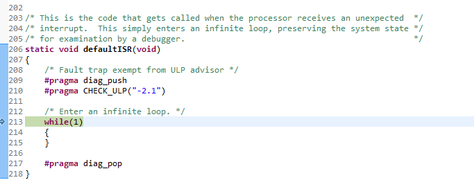
    But I keep getting stuck here because of an unexpected interrupt. Any idea how to fix this??

  • You have not declared the interrupt handler in the interrupt table. Check out the Systick example project. Check out the Startup_XXXXX.c file
  • A couple other things I've noticed.  I looked up datasheet for that part, and I think the 820Hz setting requires 0x0C, not 0x1c sent to it.

    It looks like you are running your device at 12MHz, not 3MHz.  This means MAP_SysTick_setPeriod(3000) is 0.25 milliseconds, not 1 ms as in the example.  Your loop will then run for 3000Ticks at 0.25ms/Tick or 750ms (I think you were wanting 3 seconds of data capture, so MAP_SysTick_setPeriod(12000) should be required instead.

  • Thank you so much for your help, John & Keith!
  • Thanks so much for helping me to answer this, Keith!!
  • Coming from the Arduino world, sometimes it is really nice to have something like millis().

**Attention** This is a public forum