


I am trying to use two pairs of i2c pins (EUSCI_B0 and EUSCI_B1) to communicate with two different devices that have the same slave address. I have gotten EUSCI_B0 working fine using the driver library but am having trouble with EUSCI_B1 on pins 6.4 and 6.5. When trying to read from a register, I don't see any start condition on the i2c lines and the program gets stuck polling for an interrupt flag.
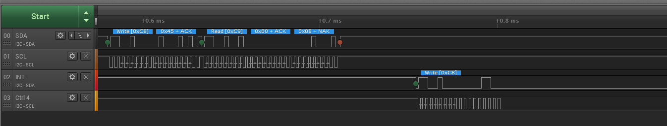
When trying to write to a register, the MSP432 addresses the slave, but the clock signal gets stuck when the slave should send an ACK. This can be seen in the saleae data capture below. The first 2 channels are the EUSCIB0 lines, and the last two channels are the EUSCIB1 lines.
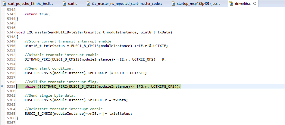
The code gets stuck here.
This is my code below


/* DriverLib Defines */
#include "driverlib.h"
#include <stdint.h>
#include <stdbool.h>
#include <string.h>
#include <stdio.h>

/* Slave Address for I2C Slave */
#define SLAVE_ADDRESS       0x64
#define NUM_OF_REC_BYTES    2

//static uint8_t Read;
static uint8_t RX;
static uint8_t TXByteCtr;
//static float horAngle, verAngle, intensity;
static uint16_t X1, X2, Y1, Y2;

/* Variables */
static uint8_t TXData[3] = {0x12, 0x5f, 0x0c};
static uint8_t RXData[NUM_OF_REC_BYTES];
static volatile uint32_t xferIndex;
static volatile bool stopSent;


/* I2C Master Configuration Parameter */
const eUSCI_I2C_MasterConfig i2cConfig =
{
        EUSCI_B_I2C_CLOCKSOURCE_SMCLK,          // SMCLK Clock Source
        3000000,                                // SMCLK = 3MHz
        EUSCI_B_I2C_SET_DATA_RATE_100KBPS,      // Desired I2C Clock of 100khz
        0,                                      // No byte counter threshold
        EUSCI_B_I2C_NO_AUTO_STOP                // No Autostop
};

#define TIMER_PERIOD    0xB71B

/* Timer_A UpMode Configuration Parameter */
const Timer_A_UpModeConfig upConfig =
{
        TIMER_A_CLOCKSOURCE_SMCLK,              // SMCLK Clock Source
        TIMER_A_CLOCKSOURCE_DIVIDER_64,          // SMCLK/1 = 3MHz
        TIMER_PERIOD,                           // 5000 tick period
        TIMER_A_TAIE_INTERRUPT_DISABLE,         // Disable Timer interrupt
        TIMER_A_CCIE_CCR0_INTERRUPT_ENABLE ,    // Enable CCR0 interrupt
        TIMER_A_DO_CLEAR                        // Clear value
};

// UART Configuration
const eUSCI_UART_Config uartConfig =
{
        EUSCI_A_UART_CLOCKSOURCE_SMCLK,          // SMCLK Clock Source

		//19200
		39,
		1,
		0,


        EUSCI_A_UART_NO_PARITY,                  // No Parity
        EUSCI_A_UART_LSB_FIRST,                  // LSB First
        EUSCI_A_UART_ONE_STOP_BIT,               // One stop bit
        EUSCI_A_UART_MODE,                       // UART mode
        EUSCI_A_UART_OVERSAMPLING_BAUDRATE_GENERATION  // Oversampling
};


bool Setup_Register(unsigned char, unsigned char, unsigned char);
bool Setup_Register1(unsigned char, unsigned char, unsigned char);
uint16_t Read_Data_Register(unsigned char);
uint16_t Read_Data_Register1(unsigned char);

void khzclock_Calibration();
void Setup_Config();
void Setup_Config1();
void UART_Transmit(uint16_t);
void ADC_Calibration(unsigned char, unsigned char);


const uint32_t default_config[] = {
        0x000c000f,
        0x00101010,
        0x0011004c,
        0x00125f0c,
        0x0013ada5,
        0x00140080,
        0x00150000,
        0x00160600,
        0x00170000,
        0x00182693,
        0x00190004,
        0x001a4280,
        0x001b0060,
        0x001c2094, // SDA/SCL pad slew rate limiter enabled
                    // INT output: enabled
                    // INT input: disabled
        0x001d0000,
        0x001e0001,
        0x001f0000,
        0x00200320,
        0x00210513,
        0x00220320,
        0x00230113,
        0x00240000,
        0x00252414,
        0x00262414,
        0x00270022,
        0x00280000,
        0x00290300,
        0x002a1770,
        0x002b157c,
        0x002c4268,
        0x002d2710,
        0x002e0000,
        0x002f0000,
        0x00300000,
        0x00310000,
        0x00320040,
        0x00330000,
        0x0034E400,
        0x00388080,
        0x00398080,
		0x003a2000,
		0x003b2000,
		0x003c2000,
		0x003d2000,
        0x003e0000,
        0x0040806d,
        0x00411f2f,
        0x00424000,
        0x00430000,
        0x00440005,
        //0x00460020, // Decimation rate for sample mode: 4
        0x00460030,
		0x004800df, // INT_STATUS register: sample interrupt
        0x00490000,
        0x00450008, // Operation Mode: Sample Mode
};


int main(void)

{
    /* Disabling the Watchdog  */
    MAP_WDT_A_holdTimer();

    /* Setting DCO to 12MHz */
    CS_setDCOCenteredFrequency(CS_DCO_FREQUENCY_12);

    /* Setting DCO to 24MHz (upping Vcore)
    FlashCtl_setWaitState(FLASH_BANK0, 2);
    FlashCtl_setWaitState(FLASH_BANK1, 2);
    MAP_PCM_setCoreVoltageLevel(PCM_VCORE1);
    CS_setDCOCenteredFrequency(CS_DCO_FREQUENCY_24);
    */

    /* Select Port 1 for I2C - Set Pin 6, 7 to input Primary Module Function,
     *   (UCB0SIMO/UCB0SDA, UCB0SOMI/UCB0SCL).
     */

    MAP_GPIO_setAsPeripheralModuleFunctionInputPin(GPIO_PORT_P1,
            GPIO_PIN6 + GPIO_PIN7, GPIO_PRIMARY_MODULE_FUNCTION);

    //2nd I2C pins
    MAP_GPIO_setAsPeripheralModuleFunctionInputPin(GPIO_PORT_P6,
                GPIO_PIN4 + GPIO_PIN5, GPIO_PRIMARY_MODULE_FUNCTION);

    /* Selecting P1.2 and P1.3 in UART mode */
    MAP_GPIO_setAsPeripheralModuleFunctionInputPin(GPIO_PORT_P1,
            GPIO_PIN1 | GPIO_PIN2 | GPIO_PIN3, GPIO_PRIMARY_MODULE_FUNCTION);

    stopSent = false;
    memset(RXData, 0x00, NUM_OF_REC_BYTES);

    /* Initializing I2C Master to SMCLK at 100khz with no autostop */
    MAP_I2C_initMaster(EUSCI_B0_BASE, &i2cConfig);
    MAP_I2C_initMaster(EUSCI_B1_BASE, &i2cConfig);

    /* Specify slave address */
    MAP_I2C_setSlaveAddress(EUSCI_B0_BASE, SLAVE_ADDRESS);
    MAP_I2C_setSlaveAddress(EUSCI_B1_BASE, SLAVE_ADDRESS);

    /* Set Master in transmit mode */
    MAP_I2C_setMode(EUSCI_B0_BASE, EUSCI_B_I2C_TRANSMIT_MODE);
    MAP_I2C_setMode(EUSCI_B1_BASE, EUSCI_B_I2C_TRANSMIT_MODE);

    /* Enable I2C Module to start operations */
    MAP_I2C_enableModule(EUSCI_B0_BASE);
    MAP_I2C_enableModule(EUSCI_B1_BASE);

    /* Configuring UART Module */
    MAP_UART_initModule(EUSCI_A0_BASE, &uartConfig);

    /* Enable UART module */
    MAP_UART_enableModule(EUSCI_A0_BASE);

    /* Enable and clear the interrupt flag */
    MAP_I2C_clearInterruptFlag(EUSCI_B0_BASE,
            EUSCI_B_I2C_TRANSMIT_INTERRUPT0 + EUSCI_B_I2C_RECEIVE_INTERRUPT0);
    MAP_I2C_clearInterruptFlag(EUSCI_B1_BASE,
                EUSCI_B_I2C_TRANSMIT_INTERRUPT1 + EUSCI_B_I2C_RECEIVE_INTERRUPT1);

    //Enable master Receive interrupt
    MAP_I2C_enableInterrupt(EUSCI_B0_BASE, EUSCI_B_I2C_TRANSMIT_INTERRUPT0);
    MAP_Interrupt_enableSleepOnIsrExit();
    MAP_Interrupt_enableInterrupt(INT_EUSCIB0);

    MAP_I2C_enableInterrupt(EUSCI_B1_BASE, EUSCI_B_I2C_TRANSMIT_INTERRUPT1);
    MAP_Interrupt_enableSleepOnIsrExit();
    MAP_Interrupt_enableInterrupt(INT_EUSCIB1);

    //MAP_Interrupt_enableSleepOnIsrExit();
    //MAP_Timer_A_configureUpMode(TIMER_A1_BASE, &upConfig);
    //MAP_Interrupt_enableInterrupt(INT_TA1_0);

    MAP_Interrupt_enableMaster();

    // set interrupt pin as input
    MAP_GPIO_setAsInputPin(GPIO_PORT_P6, GPIO_PIN7);

    printf("reading chip id and version value\n");

    while(Read_Data_Register(0x08) != 0x03fc);
    printf("setting up registers\n");
    Setup_Register(0x0f, 0x00, 0x01);       // Resetting the device
    Setup_Config();                         // 004 Configuration
    Setup_Config1();
    printf("default config loaded\n");


    Setup_Register(0x49, 0x08, 0x20);

    while (1)
    {

    	if (P6IN & BIT7) {


    			   Setup_Register(0x49, 0x08, 0x20);

    		 	 	X1 = Read_Data_Register(0x00);
    		        X2 = Read_Data_Register(0x01);
    		        Y1 = Read_Data_Register(0x02);
    		        Y2 = Read_Data_Register(0x03);

    		       MAP_UART_transmitData(EUSCI_A0_BASE, 0x00);
    		       UART_Transmit(X1);
    		       UART_Transmit(X2);
    		       UART_Transmit(Y1);
    		       UART_Transmit(Y2);


    	}


    }
}

/*******************************************************************************
 * eUSCIB0 ISR. The repeated start and transmit/receive operations happen
 * within this ISR.
 *******************************************************************************/
void EUSCIB0_IRQHandler(void)
{
    uint_fast16_t status;

    status = MAP_I2C_getEnabledInterruptStatus(EUSCI_B0_BASE);
    MAP_I2C_clearInterruptFlag(EUSCI_B0_BASE, status);

    /* If we reached the transmit interrupt, it means we are at index 1 of
     * the transmit buffer. When doing a repeated start, before we reach the
     * last byte we will need to change the mode to receive mode, set the start
     * condition send bit, and then load the final byte into the TXBUF.
     */
    if (status & EUSCI_B_I2C_TRANSMIT_INTERRUPT0)
    {
        /*if (RX == 0) {*/
            if (TXByteCtr) {
                //Send the next data and decrement the byte counter
                MAP_I2C_masterSendMultiByteNext(EUSCI_B0_BASE, TXData[3 - TXByteCtr]);
                TXByteCtr--;
            }
            else {
                if (RX == 0) {
                    MAP_I2C_masterSendMultiByteStop(EUSCI_B0_BASE);
                    stopSent = true;
                    MAP_Interrupt_disableSleepOnIsrExit();
                }
                else {
                    MAP_I2C_disableInterrupt(EUSCI_B0_BASE, EUSCI_B_I2C_TRANSMIT_INTERRUPT0);
                    MAP_I2C_setMode(EUSCI_B0_BASE, EUSCI_B_I2C_RECEIVE_MODE);
                    xferIndex = 0;
                    MAP_I2C_masterReceiveStart(EUSCI_B0_BASE);
                    MAP_I2C_enableInterrupt(EUSCI_B0_BASE, EUSCI_B_I2C_RECEIVE_INTERRUPT0);
                }
            }
    }

    /* Receives bytes into the receive buffer. If we have received all bytes,
     * send a STOP condition */
    if (status & EUSCI_B_I2C_RECEIVE_INTERRUPT0)
    {
        if(xferIndex == NUM_OF_REC_BYTES - 2)
        {
            MAP_I2C_masterReceiveMultiByteStop(EUSCI_B0_BASE);
            RXData[xferIndex++] = MAP_I2C_masterReceiveMultiByteNext(EUSCI_B0_BASE);
        }
        else if(xferIndex == NUM_OF_REC_BYTES - 1)
        {
            RXData[xferIndex++] = MAP_I2C_masterReceiveMultiByteNext(EUSCI_B0_BASE);
            MAP_I2C_disableInterrupt(EUSCI_B0_BASE, EUSCI_B_I2C_RECEIVE_INTERRUPT0);
            MAP_I2C_setMode(EUSCI_B0_BASE, EUSCI_B_I2C_TRANSMIT_MODE);
            xferIndex = 0;
            stopSent = true;
            MAP_Interrupt_disableSleepOnIsrExit();
        }
        else
        {
            RXData[xferIndex++] = MAP_I2C_masterReceiveMultiByteNext(EUSCI_B0_BASE);
        }

    }
}

void EUSCIB1_IRQHandler(void)
{
    uint_fast16_t status;

    status = MAP_I2C_getEnabledInterruptStatus(EUSCI_B1_BASE);
    MAP_I2C_clearInterruptFlag(EUSCI_B1_BASE, status);

    /* If we reached the transmit interrupt, it means we are at index 1 of
     * the transmit buffer. When doing a repeated start, before we reach the
     * last byte we will need to change the mode to receive mode, set the start
     * condition send bit, and then load the final byte into the TXBUF.
     */
    if (status & EUSCI_B_I2C_TRANSMIT_INTERRUPT1)
    {
        /*if (RX == 0) {*/
            if (TXByteCtr) {
                //Send the next data and decrement the byte counter
                MAP_I2C_masterSendMultiByteNext(EUSCI_B1_BASE, TXData[3 - TXByteCtr]);
                TXByteCtr--;
            }
            else {
                if (RX == 0) {
                    MAP_I2C_masterSendMultiByteStop(EUSCI_B1_BASE);
                    stopSent = true;
                    MAP_Interrupt_disableSleepOnIsrExit();
                }
                else {
                    MAP_I2C_disableInterrupt(EUSCI_B1_BASE, EUSCI_B_I2C_TRANSMIT_INTERRUPT1);
                    MAP_I2C_setMode(EUSCI_B1_BASE, EUSCI_B_I2C_RECEIVE_MODE);
                    xferIndex = 0;
                    MAP_I2C_masterReceiveStart(EUSCI_B1_BASE);
                    MAP_I2C_enableInterrupt(EUSCI_B1_BASE, EUSCI_B_I2C_RECEIVE_INTERRUPT1);
                }
            }
    }

    /* Receives bytes into the receive buffer. If we have received all bytes,
     * send a STOP condition */
    if (status & EUSCI_B_I2C_RECEIVE_INTERRUPT1)
    {
        if(xferIndex == NUM_OF_REC_BYTES - 2)
        {
            MAP_I2C_masterReceiveMultiByteStop(EUSCI_B1_BASE);
            RXData[xferIndex++] = MAP_I2C_masterReceiveMultiByteNext(EUSCI_B1_BASE);
        }
        else if(xferIndex == NUM_OF_REC_BYTES - 1)
        {
            RXData[xferIndex++] = MAP_I2C_masterReceiveMultiByteNext(EUSCI_B1_BASE);
            MAP_I2C_disableInterrupt(EUSCI_B1_BASE, EUSCI_B_I2C_RECEIVE_INTERRUPT1);
            MAP_I2C_setMode(EUSCI_B1_BASE, EUSCI_B_I2C_TRANSMIT_MODE);
            xferIndex = 0;
            stopSent = true;
            MAP_Interrupt_disableSleepOnIsrExit();
        }
        else
        {
            RXData[xferIndex++] = MAP_I2C_masterReceiveMultiByteNext(EUSCI_B1_BASE);
        }

    }
}

// function that loads config values to 1st slave's registers
void Setup_Config() {

    uint8_t i;
    for (i = 0; i < 54; i++) {
        unsigned char address = (unsigned char)(default_config[i] >> 16);
        unsigned char msb = (unsigned char)(default_config[i] >> 8);
        unsigned char lsb = (unsigned char)(default_config[i]);
        //printf("Address: %X\tData: %X%X\n", address, msb, lsb);

        //uint8_t verify = Setup_Register(address, msb, lsb);
        //while (verify != 1)
            //verify = Setup_Register(address, msb, lsb);

        while (Setup_Register(address, msb, lsb) != 1);
    }

}

// function that loads config values to 2nd slave's registers
void Setup_Config1() {

    uint8_t i;
    for (i = 0; i < 54; i++) {
        unsigned char address = (unsigned char)(default_config[i] >> 16);
        unsigned char msb = (unsigned char)(default_config[i] >> 8);
        unsigned char lsb = (unsigned char)(default_config[i]);
        //printf("Address: %X\tData: %X%X\n", address, msb, lsb);

        //uint8_t verify = Setup_Register(address, msb, lsb);
        //while (verify != 1)
            //verify = Setup_Register(address, msb, lsb);

        while (Setup_Register1(address, msb, lsb) != 1);
    }

}

void UART_Transmit(uint16_t data) {

       unsigned char *ptr = (unsigned char*) &data;

       MAP_UART_transmitData(EUSCI_A0_BASE, *ptr++);
       MAP_UART_transmitData(EUSCI_A0_BASE, *ptr);
       //MAP_UART_transmitData(EUSCI_A0_BASE, *ptr++);
       //MAP_UART_transmitData(EUSCI_A0_BASE, *ptr);

}

// function that writes to 1st slave's registers
bool Setup_Register(unsigned char address, unsigned char highByte, unsigned char lowByte){

    while (MAP_I2C_masterIsStopSent(EUSCI_B0_BASE) == EUSCI_B_I2C_SENDING_STOP);

    RX = 0;
    TXByteCtr = 2;

    TXData[0] = address;
    TXData[1] = highByte;
    TXData[2] = lowByte;

    MAP_I2C_disableInterrupt(EUSCI_B0_BASE, EUSCI_B_I2C_RECEIVE_INTERRUPT0);
    MAP_I2C_masterSendMultiByteStart(EUSCI_B0_BASE, TXData[0]);
    MAP_I2C_enableInterrupt(EUSCI_B0_BASE, EUSCI_B_I2C_TRANSMIT_INTERRUPT0);
    //MAP_Interrupt_enableInterrupt(INT_EUSCIB0);

    while(!stopSent)
    {
        MAP_PCM_gotoLPM0InterruptSafe();
    }

    stopSent = false;

    if (address == 0x49)
            return 1;

    uint16_t data = Read_Data_Register(address);
    //printf("Register: %x\tValue: %x\n", address, data)

    return (data == (highByte << 8)+lowByte);
}

// function that writes to 2nd slave's registers
bool Setup_Register1(unsigned char address, unsigned char highByte, unsigned char lowByte){

    while (MAP_I2C_masterIsStopSent(EUSCI_B1_BASE) == EUSCI_B_I2C_SENDING_STOP);

    RX = 0;
    TXByteCtr = 2;

    TXData[0] = address;
    TXData[1] = highByte;
    TXData[2] = lowByte;

    MAP_I2C_disableInterrupt(EUSCI_B1_BASE, EUSCI_B_I2C_RECEIVE_INTERRUPT1);
    MAP_I2C_masterSendMultiByteStart(EUSCI_B1_BASE, TXData[0]);
    MAP_I2C_enableInterrupt(EUSCI_B1_BASE, EUSCI_B_I2C_TRANSMIT_INTERRUPT1);
    //MAP_Interrupt_enableInterrupt(INT_EUSCIB0);

    while(!stopSent)
    {
        MAP_PCM_gotoLPM0InterruptSafe();
    }

    stopSent = false;

    if (address == 0x49)
            return 1;

    uint16_t data = Read_Data_Register1(address);
    //printf("Register: %x\tValue: %x\n", address, data)

    return (data == (highByte << 8)+lowByte);
}

// function that reads 1st slave's registers
uint16_t Read_Data_Register(unsigned char address) {

    while (MAP_I2C_masterIsStopSent(EUSCI_B0_BASE) == EUSCI_B_I2C_SENDING_STOP);

    RX = 1;
    TXByteCtr = 0;

    MAP_I2C_disableInterrupt(EUSCI_B0_BASE, EUSCI_B_I2C_RECEIVE_INTERRUPT0);
    MAP_I2C_masterSendMultiByteStart(EUSCI_B0_BASE, address);
    MAP_I2C_enableInterrupt(EUSCI_B0_BASE, EUSCI_B_I2C_TRANSMIT_INTERRUPT0);
    //MAP_Interrupt_enableInterrupt(INT_EUSCIB0);

    while(!stopSent)
    {
        MAP_PCM_gotoLPM0InterruptSafe();
    }

    stopSent = false;

    return (RXData[0] << 8)+RXData[1];
}

// function that reads 2nd slave's registers
uint16_t Read_Data_Register1(unsigned char address) {

    while (MAP_I2C_masterIsStopSent(EUSCI_B1_BASE) == EUSCI_B_I2C_SENDING_STOP);

    RX = 1;
    TXByteCtr = 0;

    MAP_I2C_disableInterrupt(EUSCI_B1_BASE, EUSCI_B_I2C_RECEIVE_INTERRUPT1);
    MAP_I2C_masterSendMultiByteStart(EUSCI_B1_BASE, address);
    MAP_I2C_enableInterrupt(EUSCI_B1_BASE, EUSCI_B_I2C_TRANSMIT_INTERRUPT1);
    //MAP_Interrupt_enableInterrupt(INT_EUSCIB0);

    while(!stopSent)
    {
        MAP_PCM_gotoLPM0InterruptSafe();
    }

    stopSent = false;

    return (RXData[0] << 8)+RXData[1];
}

