This thread has been locked.

If you have a related question, please click the "Ask a related question" button in the top right corner. The newly created question will be automatically linked to this question.

MSP430F5659: SPI communication with other device not from TI

Part Number: MSP430F5659
Other Parts Discussed in Thread: LMX2571

Hi there,

I'm currently working with msp430f5659 device. What I want to do is receiving data from other device using SPI. My device is FSK receiver module with the output of 0~1.5 or 0~1.8 swing of digital data.

Is it possible to use these data from other device not from TI?

Thanks

Jongchan Woo

  • Hi Jongchan!

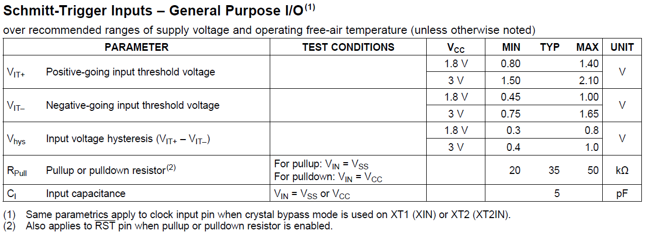
    Of course you can use the MSP430 with non-TI parts. You have to take care of the signal levels - what is the supply voltage of the MSP? It would be best if sensor and microcontroller would work with the same voltage level, of course. Otherwise level translators might be necessary. Look at this table for the threshold voltages:

    Same thing for your sensor - if it is powered with 1.8V and will receive a SPI signal of 3.3V, excessive current might flow into the device. In some cases you can work with a simple series resistor. Maybe you want to tell about the sensor you want to use and the supply voltages.

    Dennis

  • Hi Dennis!

    Thanks for answering my question. I'm using 3.3V supply for msp and 1.8V for my receiver device.

    I want to make signal of 1.8V for bit 1 and 0V for bit 0.

    I do not fully understand the table you show me, so is it okay to use my device with msp?

    Thanks
    Jongchan Woo
  • The table says that at 3V the MSP might expect a logic high level up to 2.1V in the worst case (device dependent). At 3.3V this will be even higher. 1.8V might work, but there is no guarantee. And you will have the problem with the sensor that might not like being driven by 3.3V while powered by 1.8V - you may want to use a level converter or do some level shifting by yourself.

  • Thanks a lot! I'll try it
  • Hi Dennis

    I have another question. Since there is no processor for my FSK receiver device, the only thing this device can do is convert analog signal into digital one continuously. I think that RXBUF in SPI communication is 8-bit size, so msp430 can read only 8-bit in a row. Thus, there must be some missing signal between reading two buffer's data. How can I solve this problem?

    Thanks
    Jongchan Woo
  • SPI is 8 bit per transmission - you will see that slaves normally have 8 bit or multiples of 8 bits to read or write. For a 16 bit adc result, for example, you have to receive two times 8 bits and combine the data to a 16 bit word inside your controller. Same for 24, 32 or 64 bits of data.

    A 16 bit word could look like this:

    MSB -> 1101 1001 1011 0000 <- LSB

    If you request the data you normally get the MSB first, so you could do something like this:

    // Data: MSB -> 1101 1001 1011 0000 <- LSB
    
    uint8_t data_buffer[2];
    uint16_t data_word = 0;
    
    data_buffer[0] = <request MSB>; // 1101 1001
    data_buffer[1] = <request LSB>; // 1011 0000
    
    data_word = data_buffer[0];     // 0000 0000 1101 1001
    data_word <<= 8;                // 1101 1001 0000 0000
    data_word |= data_buffer[1];    // 1101 1001 1011 0000

    Dennis

  • What I mean there are significant delay between reading/writing between two 8-bit data as shown the above figure.

    The figure shows the clk signal in SPI communication. clk goes up and down only if there is a data transfer so each yellow bar corresponds to 8-bit data transfer.

    In this figure, there are quite a big delay between each bars, which means that msp cannot get any data in this time. Since our receiver device continuously convert analog data into digital data, there should be some missing data. 

  • Well this depends on your way of receiving / writing the data from / to the slave. You might never have a 100% continuous data stream. Do you use interrupts?

  • nope I'm currently using register read and write function as followings. Can you recommend a faster function?

    unsigned short LMX2571_Reg_Read(unsigned char Reg_address)
    {
    volatile unsigned char dummy_rx;
    unsigned char SPI_Rx_buf[2];
    unsigned short retVal;
    retVal=0;
    P4OUT &= ~BIT3; //Set STE Low for Transmission

    UCA2TXBUF = (unsigned char)(0x80+Reg_address); // Send the first byte to the TX Buffer: Address of register
    while ( (UCA2STAT & UCBUSY) ); // USCI_B1 TX buffer ready?
    dummy_rx = UCA2RXBUF;
    UCA2TXBUF = 0; // Send the second byte to the TX Buffer: dummy data
    while ( (UCA2STAT & UCBUSY) ); // USCI_B1 TX buffer ready?
    SPI_Rx_buf[1] = UCA2RXBUF; // Read Rx buf: Data[23:16]
    UCA2TXBUF = 0; // Send the second byte to the TX Buffer: dummy data
    while ( (UCA2STAT & UCBUSY) ); // USCI_B1 TX
    SPI_Rx_buf[0] = UCA2RXBUF; // Read Rx buf
    // Read Rx buf: Data[7:0]
    // __delay_cycles(100000);
    P4OUT |= BIT3; // set STE HIGH at end of transmission

    retVal = SPI_Rx_buf[1];
    retVal = (retVal << 8) | SPI_Rx_buf[0];
    //retVal = (SPI_Rx_buf[1]<<16)|(SPI_Rx_buf[2]<<8)|(SPI_Rx_buf[3]);
    __delay_cycles(5);
    return retVal;
    }


    void LMX2571_Reg_Write (unsigned char reg_address, unsigned short data)
    {
    volatile unsigned char dummy_rx;
    P4OUT &= ~BIT3; //Set STE Low for Transmission
    UCA2TXBUF = (unsigned char)(reg_address); // Send the first byte to the TX Buffer: Address of register
    while ( (UCA2STAT & UCBUSY) ); // USCI_B1 TX buffer ready?
    dummy_rx = UCA2RXBUF; // Dummy Read Rx buf
    UCA2TXBUF = (unsigned char)(data >>8); // Send the second byte to the TX Buffer: Data[23:16]
    while ( (UCA2STAT & UCBUSY) ); // USCI_B1 TX buffer ready?
    dummy_rx = UCA2RXBUF; // Dummy Read Rx buf
    UCA2TXBUF = (unsigned char)(data & 0x00FF); // Send the third byte to the TX Buffer: Data[15:8]
    while ( (UCA2STAT & UCBUSY) ); // USCI_B1 TX buffer ready?
    dummy_rx = UCA2RXBUF; // Dummy Read Rx buf
    P4OUT |= BIT3; // SEN HIGH at end of transmission

    __delay_cycles(3);
    }


    I'm using LMX2571 as a transmitter, which the function name comes from.
  • Is there a problem with the speed? There is no need to use interrupts - you only want to use them if the program shall not be blocked by things that can be done in the background. What kind of data do you have to transmit and how much is it and how often dou you need to send or receive it?
  • Yes I have a speed problem. What I want to do is FSK modulation using LMX2571 and msp430f5659 as a transmitter, and another msp430f5659 with my off chip device as a receiver. The target FSK frequency is about 500khz bps. I use 20mhz and 40mhz signal as FSK frequency by writing register which is related to the output signal frequency. (I already asked several questions about this issue in e2e.ti.com/.../2128701 ). However in the current setting, the bps for FSK modulation is about 150khz even I'm using 16mhz SPI clk between MSP and LMX as shown in the figure I uploaded. I think the main reason for this delay is the poor efficiency of my register writing code. So I'm trying to optimize my register writing code.

    In short, I want to write LMX register value faster than now so that make FSK modulation frequency up to 500khz.

    Plus, I want to demodulate the received data in my device. The demodulated digital data should be transferred to msp using SPI communication. In this part, the issue is that my device just makes digital data of either 0V or 1.8V depending on received frequency "continuously". Thus, if SPI communication between my receiver device and msp is similar with that of transfer part, there would be some data loss.

**Attention** This is a public forum