This thread has been locked.

If you have a related question, please click the "Ask a related question" button in the top right corner. The newly created question will be automatically linked to this question.

CCS/MSP430G2553: MSP430 CCS #pragma method of interrupts

Part Number: MSP430G2553

Tool/software: Code Composer Studio

I'm using the MSP430G2553 launchpad with CCS. I use S2 on Port1 pin3 to cause an interrupt to the MCU.

I write my code below. 

#include "msp430g2231.h"  //Contains all definitions for registers and built-in functions 
int main(void)  //Main program
{
   WDTCTL = WDTPW + WDTHOLD; // Stop watchdog timer
  
   P1DIR |= BIT0; // Set P1.0 to output and P1.3 to input direction
   P1OUT &= ~BIT0; // set LED Off
   P1IE |= BIT3; // P1.3 interrupt enabled
   P1IES = BIT3; //Interrupt is HIGH to LOW
   P1IFG &= ~BIT3; // P1.3 interrupt flag cleared  
   __bis_SR_register(GIE); // Enable all interrupts (Clear GIE in SR)
  
   while(1) //Loop forever, we'll do our job in the interrupt routine...
   {}
}

#pragma vector=PORT1_VECTOR
__interrupt void Port_1(void)
{
    P1OUT ^= BIT0;  // Toggle P1.0
    P1IFG &= ~BIT3; // P1.3 interrupt flag cleared
}		

The intention of this question is to properly understand  #pragma vector=PORT1_VECTOR line

I now paste an excerpt from the datasheet below,

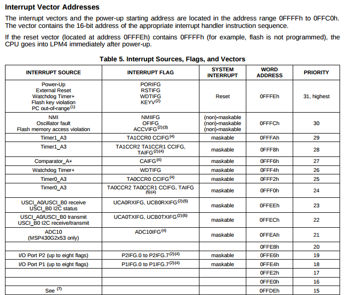
As per this, the place that must have the address of the ISR should be 0FFE4h. But I would not find the place within the CCS environment which does this operation.

However, I noticed if I write just 2 instead of PORT1_VECTOR, my code happens to work.  Below is an excerpt from the Msp430g2553 header where I view the content of PORT1_VECTOR. I find the way its defined a bit weird, in the sense that very difficult to understand. I would appreciate the uses of the following #defines could be more elaborately explained.

 My program worked when I simply had #define PORT1_VECTOR 2.

First,  I would like to know why #define PORT1_VECTOR 2 not written here. I can observe a ".int02". May be this is an integer 2? If so, why would the header file specifically mention the #define in this manner without simply stating #define PORT1_VECTOR 2 ? I would like to know that reason.  Would  truly appreciate your kind explanation there.

Secondly, where is the list of vector numbers relating to all interrupt sources? In this case, for PORT 1 interrupts it is 2, but surely in somewhere in this code, the actual memory address of the ISR must be written to the memory location 0FFE4h. Otherwise when an interrupt is triggered, the MCU would not know to direct to the ISR. I would like to see the code for this here. I could not find this implementation within the header file. 

Thank you sincerely for all your answers and time. 

  • When the compiler sees "#‍pragma vector = x", it creates a pointer to the following function, and puts that pointer into a section named ".intxx". (You can see these section names in the header file, where they are used when you include it from assembler files.)

    When the application is linked, the linker command file (named msp430‍g2553.cmd, which you should find somewhere on your computer) then specifies that the section ".int02" must be put at address 0xFFE4.

    The datasheet lists 32 possible interrupt vectors. But the first 16 are not used, so the header file just uses numbers 0 to 15 instead. (The actual number used does not really matter, as long as the header file and the linker command file agree on which number goes to which address.)

  • Hi Harry,

    You can find the answer in lnk_msp430g2553.cmd file.

    /****************************************************************************/
    /* Specify the system memory map                                            */
    /****************************************************************************/
    
    MEMORY
    {
        SFR                     : origin = 0x0000, length = 0x0010
        PERIPHERALS_8BIT        : origin = 0x0010, length = 0x00F0
        PERIPHERALS_16BIT       : origin = 0x0100, length = 0x0100
        RAM                     : origin = 0x0200, length = 0x0200
        INFOA                   : origin = 0x10C0, length = 0x0040
        INFOB                   : origin = 0x1080, length = 0x0040
        INFOC                   : origin = 0x1040, length = 0x0040
        INFOD                   : origin = 0x1000, length = 0x0040
        FLASH                   : origin = 0xC000, length = 0x3FDE
        BSLSIGNATURE            : origin = 0xFFDE, length = 0x0002, fill = 0xFFFF
        INT00                   : origin = 0xFFE0, length = 0x0002
        INT01                   : origin = 0xFFE2, length = 0x0002
        INT02                   : origin = 0xFFE4, length = 0x0002
        INT03                   : origin = 0xFFE6, length = 0x0002
        INT04                   : origin = 0xFFE8, length = 0x0002
        INT05                   : origin = 0xFFEA, length = 0x0002
        INT06                   : origin = 0xFFEC, length = 0x0002
        INT07                   : origin = 0xFFEE, length = 0x0002
        INT08                   : origin = 0xFFF0, length = 0x0002
        INT09                   : origin = 0xFFF2, length = 0x0002
        INT10                   : origin = 0xFFF4, length = 0x0002
        INT11                   : origin = 0xFFF6, length = 0x0002
        INT12                   : origin = 0xFFF8, length = 0x0002
        INT13                   : origin = 0xFFFA, length = 0x0002
        INT14                   : origin = 0xFFFC, length = 0x0002
        RESET                   : origin = 0xFFFE, length = 0x0002
    }
    
    /****************************************************************************/
    /* Specify the sections allocation into memory                              */
    /****************************************************************************/
    
    SECTIONS
    {
        .bss        : {} > RAM                  /* Global & static vars              */
        .data       : {} > RAM                  /* Global & static vars              */
        .TI.noinit  : {} > RAM                  /* For #pragma noinit                */
        .sysmem     : {} > RAM                  /* Dynamic memory allocation area    */
        .stack      : {} > RAM (HIGH)           /* Software system stack             */
    
        .text       : {} > FLASH                /* Code                              */
        .cinit      : {} > FLASH                /* Initialization tables             */
        .const      : {} > FLASH                /* Constant data                     */
        .bslsignature  : {} > BSLSIGNATURE      /* BSL Signature                     */
        .cio        : {} > RAM                  /* C I/O Buffer                      */
    
        .pinit      : {} > FLASH                /* C++ Constructor tables            */
        .binit      : {} > FLASH                /* Boot-time Initialization tables   */
        .init_array : {} > FLASH                /* C++ Constructor tables            */
        .mspabi.exidx : {} > FLASH              /* C++ Constructor tables            */
        .mspabi.extab : {} > FLASH              /* C++ Constructor tables            */
    #ifdef __TI_COMPILER_VERSION__
      #if __TI_COMPILER_VERSION__ >= 15009000
        #ifndef __LARGE_DATA_MODEL__
        .TI.ramfunc : {} load=FLASH, run=RAM, table(BINIT)
        #else
        .TI.ramfunc : {} load=FLASH | FLASH2, run=RAM, table(BINIT)
        #endif
      #endif
    #endif
    
        .infoA     : {} > INFOA              /* MSP430 INFO FLASH Memory segments */
        .infoB     : {} > INFOB
        .infoC     : {} > INFOC
        .infoD     : {} > INFOD
    
        /* MSP430 Interrupt vectors          */
        TRAPINT      : { * ( .int00 ) } > INT00 type = VECT_INIT
        .int01       : {}               > INT01
        PORT1        : { * ( .int02 ) } > INT02 type = VECT_INIT
        PORT2        : { * ( .int03 ) } > INT03 type = VECT_INIT
        .int04       : {}               > INT04
        ADC10        : { * ( .int05 ) } > INT05 type = VECT_INIT
        USCIAB0TX    : { * ( .int06 ) } > INT06 type = VECT_INIT
        USCIAB0RX    : { * ( .int07 ) } > INT07 type = VECT_INIT
        TIMER0_A1    : { * ( .int08 ) } > INT08 type = VECT_INIT
        TIMER0_A0    : { * ( .int09 ) } > INT09 type = VECT_INIT
        WDT          : { * ( .int10 ) } > INT10 type = VECT_INIT
        COMPARATORA   : { * ( .int11 ) } > INT11 type = VECT_INIT
        TIMER1_A1    : { * ( .int12 ) } > INT12 type = VECT_INIT
        TIMER1_A0    : { * ( .int13 ) } > INT13 type = VECT_INIT
        NMI          : { * ( .int14 ) } > INT14 type = VECT_INIT
        .reset       : {}               > RESET  /* MSP430 Reset vector         */
    }
    
    /****************************************************************************/
    /* Include peripherals memory map                                           */
    /****************************************************************************/
    
    -l msp430g2553.cmd


**Attention** This is a public forum