Other Parts Discussed in Thread: MSP430WARE
I'm using the MSP430F6721 to communicate with TI's TMP007 temperature sensor using I2C and TI's driverlib. I can read important data from the TMP007 (thermopile voltage, die temperature, calibrated temperature), but I cannot reliably write data to it. When I try to write to the TMP007 (to the configuration register, or to one of the coefficient registers) I get a partial write, where the register address is missing.
I previously asked for feedback on my I2C write-then-read function, which works wonderfully.
Here is my I2C write function.
/**************************************************************************//**
 * @brief       Write to  TMP007 Register using I2C.
 * @param[in]   address - I2C device address
 * @param[in]   reg - TMP007 register to act upon
 * @param[in]   data - data to write to the TMP007 chip
 * @retval      true for success; false otherwise
 *****************************************************************************/
static bool tempWriteReg (uint8_t address, uint8_t reg, _q4_t data)
{
    bool result = false;                // pessimistic return value
    uint8_t temp[2] = {0,0};            // data to send over I2C

    // Form the message.
    temp[0] = (uint8_t)(data >> 8);
    temp[1] = (uint8_t)(data & 0x00FF);

    do  // This structure will handle errors nicely.
    {
        // Set the slave address of the sensor we wish to talk to.
        EUSCI_B_I2C_setSlaveAddress(I2C_BASEADDR, address);

        // Set write mode.
        EUSCI_B_I2C_setMode(I2C_BASEADDR, EUSCI_B_I2C_TRANSMIT_MODE);

        // Pat the watchdog before while loops in the following functions.
        watchdog_update();

        // Write the register to the sensor.
        // Send START + address, followed by 3 byte message, followed by STOP.
        result = EUSCI_B_I2C_masterSendMultiByteStartWithTimeout(I2C_BASEADDR, reg, TEMP_TIMEOUT);
        if (result == false)
            break;

        result = EUSCI_B_I2C_masterSendMultiByteNextWithTimeout(I2C_BASEADDR, temp[0], TEMP_TIMEOUT);
        if (result == false)
            break;

        result = EUSCI_B_I2C_masterSendMultiByteFinishWithTimeout(I2C_BASEADDR, temp[1], TEMP_TIMEOUT);
    } while (false);

    return result;
}
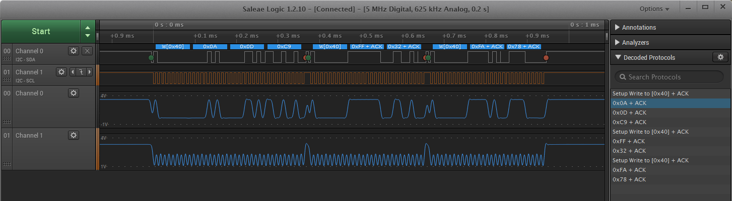
Below is a capture of I2C data when executing the following three lines of code, using a Saleae Logic protocol analyzer.
#define TMP007_ADDRESS 0x40    // 7-bit address of sensor

#define TMP007_REG_S0 0x0A    // S0 Coefficient Register
#define TMP007_REG_B0 0x0D    // B0 Coefficient Register
#define TMP007_REG_B1 0x0E    // B1 Coefficient Register

tempWriteReg(TMP007_ADDRESS, S0_COEFF_REG_ADDR, 0x0DC9);
tempWriteReg(TMP007_ADDRESS, B0_COEFF_REG_ADDR, 0xFF32);
tempWriteReg(TMP007_ADDRESS, B1_COEFF_REG_ADDR, 0xFA78);
Green dots indicates a start condition; red dots indicate a stop condition. The blue waveform is the analog waveform on the bus. As you can see, while there should be four bytes in each transaction, there are only three bytes in the 2nd and 3rd transaction.
Am I doing something obviously wrong? Also, is there an I2C example for the MSP430F6721 that uses driverlib? I was unable to find one in MSP430ware.