This thread has been locked.

If you have a related question, please click the "Ask a related question" button in the top right corner. The newly created question will be automatically linked to this question.

MSP430FR5969: SPI long delay between bytes

Part Number: MSP430FR5969

Simply put, I have what I would expect a reasonably fast write routine to push some data to a SPI slave. However this takes ~20µs between write operations (between each byte) for some reason. I've been going over the disassembly but I can't really figure out why should it take so long. MCLK is @ 8MHz so 20µs should work out to some 160 clock cycles.. There's nothing that should result in that kind of numbers that I can tell.

Any ideas what's going on here?

SPI_READ equals six bytes here. 

	for(spi_read.indexw=0;spi_read.indexw<SPI_READ;spi_read.indexw++){
		/*
		 * Busy means we haven't got the expected byte yet.
		 */
		spi_write.busy=1;
		spi_read.busy=1;

		//Transmit Data to slave
	    EUSCI_B_SPI_transmitData(EUSCI_B0_BASE, spiwrites[spi_read.indexw]);
	    //wait until packet write is done
	    //while(spi_write.busy)
	    while(!UCB0IFG_H&UCB0IFG)
	    {
	    	__no_operation();
	    }
	}

And the ISR, TX interrupt is not enabled.

/*Internal SPI bus ISR
 * v0.9x use B0 instead of A1
 */

#if defined(__TI_COMPILER_VERSION__) || defined(__IAR_SYSTEMS_ICC__)
#pragma vector=USCI_B0_VECTOR
__interrupt
#elif defined(__GNUC__)
__attribute__((interrupt(USCI_B0_VECTOR)))
#endif
void USCI_B0_ISR(void)
{
    switch(__even_in_range(UCB0IV,4))
    {
    //Vector 2 - RXIFG
    case 2:
        spi_read.data[spi_read.indexr] = EUSCI_B_SPI_receiveData(EUSCI_B0_BASE);
        spi_read.indexr++;
		spi_read.busy=0;
        //stay awake after interrupt
        _low_power_mode_off_on_exit();
        break;
    //Vector 4 TXIFG
    case 4:
    	spi_write.busy=0;
    break;
    default: __never_executed();
    }


}

  • Hi Olli,

    What is your SMCLK frequency? Can you provide any logic analyzer or oscilloscope screenshots of the SPI lines? The high-level DriverLib API involves longer-than-expected delays with some functionality but EUSCI_B_SPI_transmitData is straightforward. Most of this time is probably spent waiting for the byte to be written out of the TX buffer clearing the UCB0IFG flag. You could try running some C code instead as a comparison.

    Regards,
    Ryan
  • SMCLK is 4MHz, actual byte goes out exactly as expected in a nice 4Mbps burst rat-a-tat-tat and then a long fat wait until the next byte starts. I can get you an oscilloscope screenshot in Monday but it'll just show you what I described.. I was fiddling a bit with optimizations and the like, my system heartbeat (20µs) was firing during that wait making things worse (around 30µs between bytes) so I increased the heartbeat to 500µs which together with higher level optimizations reduced the byte-to-byte gap to 16µs. 

    I could always rewrite the routine to use DMA burst instead as it's quite a set piece operation but I'm already using 2 DMA channels for external SPI bus operations.. And before you ask, no, the external I/O was not active at the time. 

    In fact it doesn't seem like that NOP is firing much. I put a counter there and it hardly increases. 

  • The statement "while(!UCB0IFG_H&UCB0IFG)" make no sense whatsoever. UCB0IFG_H is the upper half of the UCB0IFG register, and "!" has higher precedence than "&".
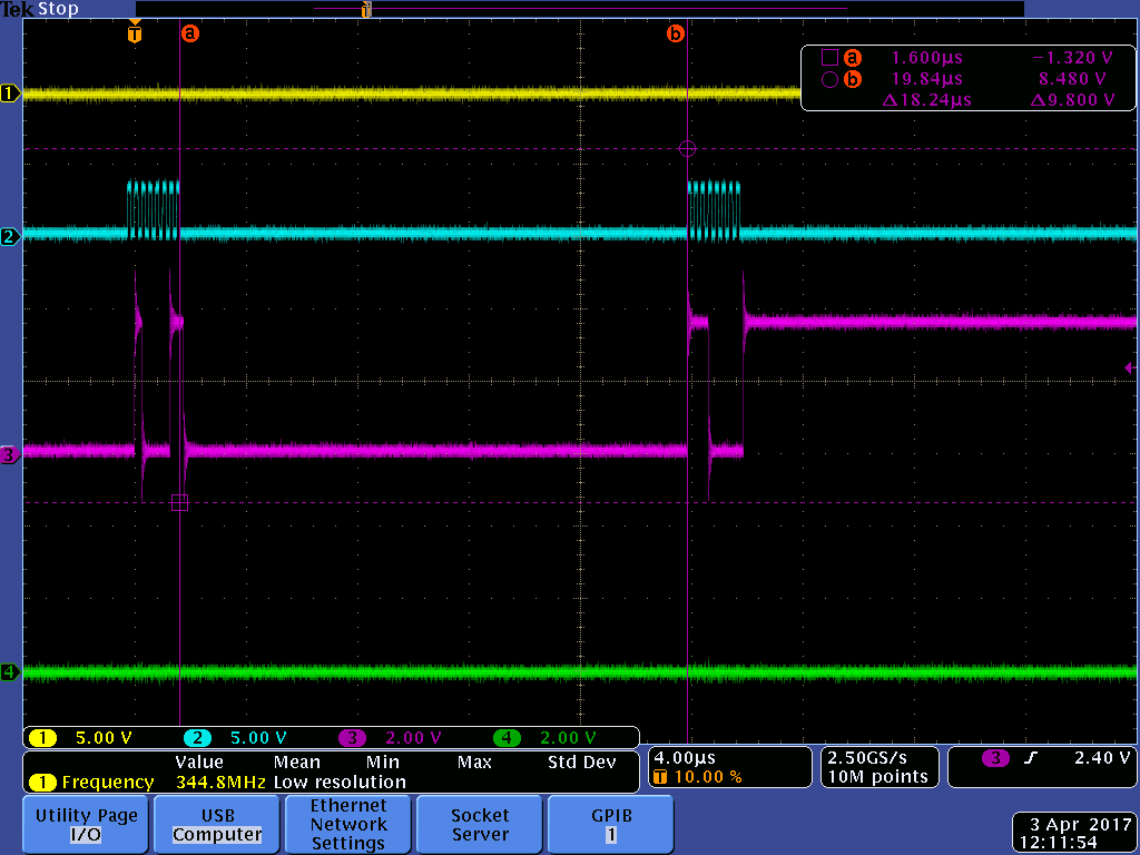
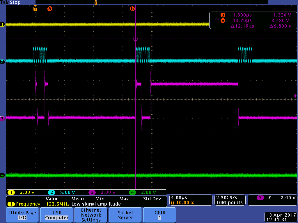
  • Here's the oscilloscope image. As I said, it just shows you the 4MHz clock plus ~20µs gap between bytes. This is generated with the original code that used TX IFG to clear a flag value, it's a bit slower. Actually a LOT slower than it should be, again. 

    And after I fixed the IFG polling bit the delay drops by 6µs.. So eliminating an ISR from triggering, setting a flag and exiting takes 6µs?? Still mondo delay between bytes there. 

    And before you ask, here are the clock registers. DCO @ 16MHz, MCLK @ 8MHz, SMCLK @ 4MHz and FRAM has no wait states (not shown). 

  • Right you are. Teaches me to assume that was a bitmask. That's not the problem here thought, this does not generate any delays as the TX flag is already up by the time the while loop is executed (TX byte has ample time to be pushed out with these delays..)

    I changed it to:
    while(!UCB0IFG_L&0x2)
  • Some more fiddling with this. Executing this takes 0x42 timer ticks @ 250ns timer clock i.e. freaking slow. As a curious coincidence it's 16.25µs.. 

    	    loop=Timer_A_getCounterValue(TIMER_A1_BASE);
    		//Transmit Data to slave
    	    EUSCI_B_SPI_transmitData(EUSCI_B0_BASE, spiwrites[spi_read.indexw]);
    		//UCB0TXBUF=spiwrites[spi_read.indexw];
    	    //wait until packet write is done
    	    loop=Timer_A_getCounterValue(TIMER_A1_BASE)-loop;

    If I write directly to the UCB0TXBUF, this drops to 0x18 or 6µs. A bit better but still really slow. It seems that a) for some reason function calls and ISR takes really long time here and b) just writing to that address is really really slow. Disassembly looks like this:

     99     		UCB0TXBUF=spiwrites[spi_read.indexw];
            $C$L6:
    01148c:   01CF                MOVA    SP,R15
    01148e:   425E 1C3B           MOV.B   &0x1c3b,R14
    011492:   0FEE                ADDA    R15,R14
    011494:   4E6F                MOV.B   @R14,R15
    011496:   4F82 064E           MOV.W   R15,&USCI_B0__SPI_Mode_UCB0TXBUF__SPI
    102     	    while(!UCB0IFG_L&0x2)


  • "!" has higher precedence than "&". And please don't use magic numbers:

    while (!(UCB0IFG & UCTXIFG))
        ;
  • I figured this out finally. MSP430 is just that slow @ 8MHz.. You get 750ns interrupt latency (6 cycles @ 8MHz) right away. Then you get more delay fiddling with the interrupt flag switch. And more delay coming back from the ISR.

    Disabling the ISR outright and replacing the write code by this shaves the inter-byte delay from 12.5µs to 2.5µs which is probably as good as you can do without assembler and/or DMA. That works out to 4.5µs per byte which is about 1.75Mbps. 

    	for(spi_read.indexw=SPI_READ-1;spi_read.indexw;spi_read.indexw--){
    		//Transmit Data to slave
    		UCB0TXBUF=spiwrites[spi_read.indexw];
    	    //wait until byte read is done
    	    while(!UCB0IFG_L&0x1)
    	    {
    	    	__no_operation();
    //		    __delay_cycles(0x10);
    	    }
    	    spi_read.data[spi_read.indexw] = UCB0RXBUF;
    	}

  • You can use DMA to further improve SPI timing.

  • I did go looking for that interrupt flag define but I couldn't find it. It's in-between mass of I2C and UART definitions, just two lines.. And, yes, the precedence matters. That slows things down to ~1.45Mbps but on the other hand you don't get lost RX packets which is nice.

    .. Hmm, removing that NOP from the while loop shaves ~800ns off the loop time which is a bit unexpected.. 

  • Olli Mannisto said:

    Disabling the ISR outright and replacing the write code by this shaves the inter-byte delay from 12.5µs to 2.5µs which is probably as good as you can do without assembler and/or DMA. That works out to 4.5µs per byte which is about 1.75Mbps. 

    	for(spi_read.indexw=SPI_READ-1;spi_read.indexw;spi_read.indexw--){
    		//Transmit Data to slave
    		UCB0TXBUF=spiwrites[spi_read.indexw];
    	    //wait until byte read is done
    	    while(!UCB0IFG_L&0x1)
    	    {
    	    	__no_operation();
    	    }
    	    spi_read.data[spi_read.indexw] = UCB0RXBUF;
    	}

    Do you only want to write data to the slave, or do you need to read back as well?

    If you only need to write it's possible to get continuous SPI output at 4MHz with MCLK set to 8MHz, without using assembly or DMA. Instead of polling while(!(UCB0IFG & UCRXIFG)) as in the code above, you can poll while(!(UCB0IFG & UCTXIFG)). UCTXIFG is set as soon as TXBUF is copied to the output shift register, so you get to load the next byte in parallel with the USCI shifting out the first byte onto the wire. By waiting for UCRXIFG instead the USCI is already stalling before you get chance to load the next byte.

**Attention** This is a public forum