This thread has been locked.

If you have a related question, please click the "Ask a related question" button in the top right corner. The newly created question will be automatically linked to this question.

Msp430g2553: Msp430g2553-ccs

Part Number: MSP430G2553
Other Parts Discussed in Thread: MAX3232

Sir the problem I am facing is when I upload blinking  CCS program to msp430g2553. It's working fine!! But when I am uploading UART code. It's not working!! Can I know what might be the problem????

  • Please explain your UART setup in full detail, both software and hardware.  List the example are you using, what you are attempting to communicate with, the FET tool and EVM used, which device connections are made, etc.

    Edit: What JMG says here.

    Regards,
    Ryan

  • sir 1st of all sorry for the delay. My entire project is auto-irrigation system. So in my project xigbee and gsm module is used. zigbee for making a set of wireless sensor network and gsm to know the status of motor via sms. So i need two uarts thus i am using two msp430 for this pupose. The problem is when i upload blink code its working but when i use to upload uart code it uploads successfully but it's not working. If i replace the I.C msp430g2553 with another new msp430g2553  it starts working . So probably this might be uart txp1.2 rx p1.1 problem and this problem i faced in 3 ics  but this cannot be suitable for long run. So i need advice how can i make sure that any configuration has changed or uart pins problem and if so then what is the solution. How can i use it for long run. I am using ccs ide. Please help me out sir!! If more information is needed please let me know sir. Thank you for the help sir!!
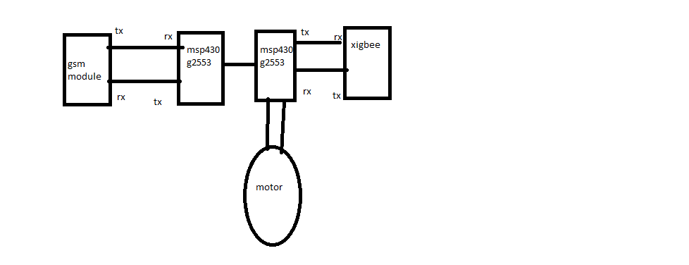
  • Your diagram is useful for orientation, but without part numbers and interconnects for "GSM", "Zigbee", and "motor" it's hard to go beyond generalities.

    My information is a bit dated, but when I see "GSM module" I think first of (a) "5 volts", which is incompatible with MSP430 (all 3.3V) and (b) "power hog", which will tax your supply and cause droops. The MSP430 is pretty tough, and may in some cases appear to run for a short time when given 5V, but you really need level converters.

    When I see "motor" I first think of (1) noise (2) power spikes (3) "power hog". Are you isolating the motor both physically and electrically?

    More generally: Your diagram describes a moderately complex system. Have you tried debugging piecewise, so you can be sure that the parts work on their own before combining them?
  • Sir thank you for you reply!!! Sir sry I couldn't give more information. Basically the whole project is auto irrigation system. There are two different parts of this project
    1) forming a wireless sensor network where at each node (basically router) the setup contains 1 MSP and one zigbee and 5 moisture sensor. After reading the moisture sensor using
    Multiple channel adc conversion the data is appended to zigbee and sent to the network coordinator.
    2) now this coordinator contains zigbee to recieve and 1 msp430 to extract the data from the zigbee frame and comparing it to threshold to trigger the really which basically turn on / off the motor.
    3) now if the motor is on/ off this setup should send the farmer an SMS about the status of the motor.So GSM is required here.
    And hence I used one more msp430g2553 and and connected one gpio pin to coordinator microcontroller to know the status. And accordingly send SMS via GSM.
    I have successfully implemented this whole system and part wise also it's working but the problem is after few days GSM part stops working and when I cross checked I recognized that my tx-rx pin gone because I am not able to see status on Bluetooth or putty also. But for the long run system this problem is very serious problem. So basically I need help how to get out of this problem?? Should I use max3232!!
    One more thing I have two GSM module one is TTL level another is rs232 level. What I see is when I connect rs232 based GSM I am getting call sms everything but after some times TX RX pin stops working. But when I connected TTL based GSM module I was getting error response to the AT commands. But this TTL based GSM module is working fine using TTL at 5v using putty.
    One more information GSM,relay and msp430g2553 is powered with one source but 3(lm2596S) different buck converters are used such as 3.3v for MSP, 5v for relay and 9v for GSM module. with common ground
  • The MSP430 cannot interact with any voltages above 3.6 V and as such some form of level translator will be necessary to communicate with devices operating at 5 or 9 volts.

    Regards,
    Ryan

**Attention** This is a public forum