This thread has been locked.

If you have a related question, please click the "Ask a related question" button in the top right corner. The newly created question will be automatically linked to this question.

CCS/MSP430G2553: Timer Pulse Width Modulation using Interrupts Example

Part Number: MSP430G2553

Tool/software: Code Composer Studio

Hi, can someone give me an example of using TimerA to generate a PWM using interrupts?

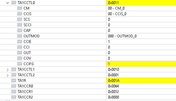
My code keeps flagging CCR0 interrupt. 

// MSP430G2553
// ---------------
// |                       |
// |                       |
// |       P1.3/TA1|-->PWM
//

int main(void)
{
WDTCTL = WDTPW + WDTHOLD; // Stop WDT

P1DIR |= BIT3; // PWM output from Timer

TA1CCR0 = 100; //frequency
TA1CCR1 = 50; // duty cycle
TA1CCTL0 |= CCIE + OUTMOD_7; // TBCCR0 interrupt enabled
TA1CCTL1 |= CCIE + OUTMOD_7; // TBCCR0 interrupt enabled
__bis_SR_register(GIE); // Enter LPM0, enable interrupts

  while(1){}

#pragma vector=TIMER1_A0_VECTOR
__interrupt void TIMER1_A0_ISR (void)
{
        P1OUT |= BIT3; 
}

#pragma vector=TIMER1_A1_VECTOR
__interrupt void TIMER1_A1_ISR(void)
{
/* Any access, read or write, of the TBIV register automatically resets the
highest "pending" interrupt flag. */
switch( __even_in_range(TA1IV,14) )
{
case 0: break; // No interrupt
case 2:

        P1OUT &= ~BIT3; // End PWM

break; 
case 4:
break; 
case 6: break; // CCR3 not used
case 8: break; // CCR4 not used
case 10: break; // CCR5 not used
case 12: break; // CCR6 not used
case 14: // overflow
break;
default: break;
}
}

Sorry for the unformatted code. Hope it makes sense.

thank you,

Scott

  • To get formatted code, use the "Insert Code" button.

    What exactly do you mean with "keeps flagging CCR0 interrupt"? As far as I can see, you never start the timer, so nothing should happen.

    Please ensure that comments are correct; this code does not enter LPM0.

    TI's example code is not always perfect; please use symbols like TA1IV_TACCR1 instead of magic numbers like 2.

  •  MSP430G2553
    // ---------------
    // |                       |
    // |                       |
    // |       P1.3/TA1|-->PWM
    //
    
    int main(void)
    {
    WDTCTL = WDTPW + WDTHOLD; // Stop WDT P1DIR |= BIT3; // PWM output from Timer TA1CCR0 = 100; //frequency TA1CCR1 = 50; // duty cycle TA1CCTL0 |= CCIE + OUTMOD_7; // TBCCR0 interrupt enabled TA1CCTL1 |= CCIE + OUTMOD_7; // TBCCR0 interrupt enabled __bis_SR_register(GIE); // enable interrupts

                      __no_operation(); // For debugger
                      TA1CTL = ID_0 + TASSEL_2 + MC_1 + TACLR; // up mode, SMCLK, clear 

           while(1){}
    
    #pragma vector=TIMER1_A0_VECTOR
    __interrupt void TIMER1_A0_ISR (void)
    {
            P1OUT |= BIT3; 
    }
    
    #pragma vector=TIMER1_A1_VECTOR
    __interrupt void TIMER1_A1_ISR(void)
    {
    /* Any access, read or write, of the TBIV register automatically resets the
    highest "pending" interrupt flag. */
    switch( __even_in_range(TA1IV,14) )
    {
    case 0: break; // No interrupt
    case 2:
    
            P1OUT &= ~BIT3; // End PWM
    
    break; 
    case 4:
    break; 
    case 6: break; // CCR3 not used
    case 8: break; // CCR4 not used
    case 10: break; // CCR5 not used
    case 12: break; // CCR6 not used
    case 14: // overflow
    break;
    default: break;
    }
    }

     I'm not sure if I used the "insert code" correctly. I think I still didn't do it right because it still looks unformated. I copied directly from CCS in a Windows environment. Maybe there's a better way to insert CCS code (and still be able to scrape off the stuff I don't want).

    Otherwise, I reposted my code, this time setting the TA1CTL register to start the timer. 

    Also, I have magic numbers for TA1CCR0 and TA1CCR0, but the are commented with frequency and PWM. Sorry.

    They other magic numbers are in the ISR, which I also left there because this is code that I copied from the TI resource manager.

    thank you and I hope this is clearer. Let me know if it's nonstandard/unclear.

  • What I meant by "keeps flagging the CCR0 interrupt" is this: I single-step thru my code, then TAIR counts to TA1CCR1, which sets the CCR1 interrupt flag CCIFG. Then it calls the TIMER1_A1 ISR. This part seems to work correctly (actually I set a break point in TIMER1_A1 becuase you cannot single-step into it because according toanother post the debugger will corrupt TAIV). But otherwise it seems to work as expected.

    Then I single-step and watch TAIR count to TA1CCR1. When TAIR counts to TA1CCR1, it runs TIMER1_A0_ISR. I can see it set TA1CCR0 CCIFG. Then single-stepping inside TIMER1_A0_ISR, CCIFG is reset. But then stepping again CCIFG is set! So I never exit TIMER1_A0_ISR.

    Also, my understanding is that TAIR should be reset by CCR0 but I don't see this happening.
    thank you,
    Scott
  • Correction:
    What I meant by "keeps flagging the CCR0 interrupt" is this: I single-step thru my code, then TAIR counts to TA1CCR1, which sets the CCR1 interrupt flag CCIFG. Then it calls the TIMER1_A1 ISR. This part seems to work correctly (actually I set a break point in TIMER1_A1_ISR becuase you cannot single-step into it because according toanother post the debugger will corrupt TAIV). But otherwise it seems to work as expected.

    Then I single-step and watch TAIR count to TA1CCR0. When TAIR counts to TA1CCR0, it runs TIMER1_A0_ISR. I can see it set TA1CCR0 CCIFG. Then single-stepping inside TIMER1_A0_ISR, CCIFG is reset. But then stepping again CCIFG is set! So I never exit TIMER1_A0_ISR.

    Also, my understanding is that TAIR should be reset by CCR0 but I don't see this happening.
  • Just because TI uses magic numbers doesn't mean that you have to slavishly follow it; you can do better:

    switch (TA1IV)
    {
    case TA1IV_TACCR1:
        P1OUT &= ~BIT3;
        break;
    case TA1IV_TACCR2:
        break;
    case TA1IV_TAIFG:
        break;
    default:
        break;
    }

    (And because of using magic numbers, whoever wrote that code didn't notice that the G2553 timers do not have six CCRs.)

    Anyway, how fast is your clock? I doubt that you can single-step fast enough to notice the timer running through 100 ticks. (To observe the PWM output, use an oscilloscope or a logic analyzer.)

  • //  MSP430G2553 
    //
    //  Description: Uses timer TA1.
    //  TA1: PWM output
    //
    //
    //           MSP430G2553
    //         ---------------
    //        |               |
    //        |               |
    //        |       P1.3/TA1|-->PWM
    //
    //
    #include <msp430.h>
    #define TA1IV_TACCR1		2
    #define TA1IV_TACCR2		4
    #define PWM_FREQUENCY		100
    #define PWM_DUTY_CYCLE		50
    
    int main(void)
    {
    	  WDTCTL = WDTPW + WDTHOLD;                 // Stop WDT
    	  P1DIR |= BIT3;                          	// PWM output from TimerA
    
    	  TA1CCR0 = PWM_FREQUENCY;					//frequency
    	  TA1CCR1 = PWM_DUTY_CYCLE;                 // duty cycle
    	  TA1CCTL0 |= CCIE;           			    // TBCCR0 interrupt enabled
    	  TA1CCTL1 |= CCIE;         			     // TBCCR1 interrupt enabled
    
    	  __bis_SR_register(GIE);       			//enable interrupts
    	  __no_operation();                         // For debugger
    	  TA1CTL = ID_0 + TASSEL_2 + MC_1 + TACLR;				// up mode, div 8
    
    	  while(1){
    		  /*
    		   * some code
    		  		*/
    		  __no_operation();
    	      }
    
    }
    
    
    // PWM output
    // This ISR determines the frequency of the PWM signal by setting TA1 CCR0
    // TIMER1_A0 = Timer A1 CCR0
    #pragma vector=TIMER1_A0_VECTOR
    __interrupt void TIMER1_A0_ISR (void)
    {
    	P1OUT |= BIT0;							//start PWM
    }


    // Timer_A3 Interrupt Vector (TBIV) handler
    // PWM output
    // This ISR determines the pulse width of the PWM signal by setting TA1 CCR1
    // TIMER1_A1 = Timer A1 CCR1-?
    #pragma vector=TIMER1_A1_VECTOR
    __interrupt void TIMER1_A1_ISR(void)
    {
      /* Any access, read or write, of the TBIV register automatically resets the
      highest "pending" interrupt flag. */
      switch( __even_in_range(TA1IV,14) )
      {
        case  0: break;                          // No interrupt
        case  TA1IV_TACCR1:
        		 P1OUT &= ~BIT3;                  // End PWM
        		 break;                          // CCR1 pulse width
        case  TA1IV_TACCR2:
        		 break;                          // CCR2 not used
        default: break;
      }
    }


  • OK, I cleaned up my code. Does this look better? Thanks for the tips and I see what you mean about the magic numbers. Let me know if you see any more problems with coding style.

    Now It stills is stuck in TIMER1_A0_ISR. I tried resetting CCIFG inside the ISR but something is still settting it, so I never exit the CCR0 interrupt service routine.
    thank you,
    Scott
  • The TA1IV_TACCRx symbols are already defined in the header file; don't redefine them.

    Section 12.2.6.1 of the User's Guide says:

    The TACCR0 CCIFG flag is automatically reset when the TACCR0 interrupt request is serviced.

    So it is not possible for the TIMER1_A0_ISR to become stuck.

    The interrupt handler is executed repeatedly because the timer continues running. If you don't want it to run again, stop the timer.

  • //
    //           MSP430G2553
    //         ---------------
    //        |               |
    //        |               |
    //        |       P1.3/TA1|-->PWM
    //
    //
    #include <msp430.h>
    #define PWM_FREQUENCY		100
    #define PWM_DUTY_CYCLE		50
    
    int main(void)
    {
    	  WDTCTL = WDTPW + WDTHOLD;                 // Stop WDT
    	  P1DIR |= BIT3;                          	// PWM output from TimerA
    
    	  TA1CCR0 = PWM_FREQUENCY;					//frequency
    	  TA1CCR1 = PWM_DUTY_CYCLE;                 // duty cycle
    	  TA1CCTL0 |= CCIE;           			    // TBCCR0 interrupt enabled
    	  TA1CCTL1 |= CCIE;         			     // TBCCR1 interrupt enabled
    
    	  __bis_SR_register(GIE);       			//enable interrupts
    	  __no_operation();                         // For debugger
    	  TA1CTL = ID_0 + TASSEL_2 + MC_1 + TACLR;				// up mode, div 8
    
    	  while(1){
    		  /*
    		   * some code
    		  		*/
    		  __no_operation();
    	      }
    
    }
    
    
    // PWM output
    // This ISR determines the frequency of the PWM signal by setting TA1 CCR0
    // TIMER1_A0 = Timer A1 CCR0
    #pragma vector=TIMER1_A0_VECTOR
    __interrupt void TIMER1_A0_ISR (void)
    {
    	P1OUT |= BIT3;							//start PWM
    }


    // Timer_A3 Interrupt Vector (TBIV) handler
    // PWM output
    // This ISR determines the pulse width of the PWM signal by setting TA1 CCR1
    // TIMER1_A1 = Timer A1 CCR1-?
    #pragma vector=TIMER1_A1_VECTOR
    __interrupt void TIMER1_A1_ISR(void)
    {
      /* Any access, read or write, of the TBIV register automatically resets the
      highest "pending" interrupt flag. */
      switch( __even_in_range(TA1IV,14) )
      {
        case  0: break;                          // No interrupt
        case  TA1IV_TACCR1:
        		 P1OUT &= ~BIT3;                  // End PWM
        		 break;                          // CCR1 pulse width
        case  TA1IV_TACCR2:
        		 break;                          // CCR2 not used
        default: break;
      }
    }


  • OK, I removed my redefinition of TA1IV_TACCRx (the compiler warned me about it).

  • I understand your reference to User Guide that the CCIFG is automatically reset. And I observe it in CCS debug session it is reset upon entering ISR. However, it is again set again before exiting  the ISR. The image shows that CCIFG is set even though the counter TA1R < TA1CCR0, the compare register. Why is it being set?

    thank you,

    Scott

**Attention** This is a public forum