


Part Number: MSP430F5529
Max SPI data throughput cannot go above 120kbit/s but need ~ 240kbit/s.
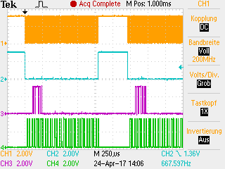
This picture shows two SPI transactions four bytes each as overview
This picture shows the zoom-in of the first transaction:
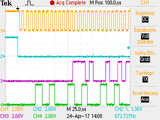
Here the lower 4. signal is active during the interrupt routine. In the source code (attached
#include <msp430.h>
#include <string.h>

#define FALSE 0
#define TRUE  1
#define BOOL  int

#define RX_TX_SIZE 16
#define RX_BUF_SIZE  (RX_TX_SIZE * 4)
#define TX_BUF_SIZE  (RX_TX_SIZE * 2)

BOOL gRxFlag = FALSE;
int gReadIdx = 0;
int gWriteIdx = TX_BUF_SIZE / 2;
int gRxIdx = 0;
int gTxIdx = 0;
unsigned int gCounter = 0;
unsigned int Counter = 0;
unsigned char gTxBuffer[TX_BUF_SIZE];
unsigned char gRxBuffer[RX_BUF_SIZE];


void initIf()
{
  UCSCTL2 = 0x003F;                         // Set max speed
  WDTCTL = WDTPW+WDTHOLD;                   // Stop watchdog timer

  while(!(P2IN&0x80));                      // If clock sig from mstr stays low,
                                            // it is not yet in SPI mode

  P2SEL |= BIT7;                            // P2.7 option select
  P3SEL |= BIT2+BIT3+BIT4;                  // P3.2,3,4 option select
  P3DIR &= ~BIT2;             				// Set P3.2 to Input direction
  P3REN &= ~BIT2;             				// P3.2 Pulldown/up disabled
  P3DIR &= ~BIT3;             				// Set P3.3 to Input direction
  P3REN &= ~BIT3;             				// P3.3 Pulldown/up disabled
  P3DIR |= BIT4;              				// Set P3.4 to Output direction
  P8DIR |= BIT1;              				// Set P8.1 to Output direction
  UCA0CTL1 |= UCSWRST;                      // **Put state machine in reset**
  UCA0CTL0 |= 0x65;                         // 4-pin, 8-bit SPI slave,
                                            // Clock polarity high, MSB,
                                            // Slave enabled when UCxSTE = 0

  //UCA0TXBUF = 0xFF; really needed???

  UCA0CTL1 &= ~UCSWRST;                     // **Initialize USCI state machine**
  UCA0IE |= UCTXIE | UCRXIE;                // enable SPI interrupt

  __bis_SR_register(GIE);                   // Enter LPM3, enable interrupts,
}

int main(void)
{
  int i;

  initIf();

  for (i = 0; i < RX_BUF_SIZE; ++i) gRxBuffer[i] = 0;
  for (i = 0; i < TX_BUF_SIZE; ++i) gTxBuffer[i] = 0;

//  UCA0TXBUF = gTxBuffer[gTxIdx]; //needed?
//  ++gTxIdx;  //needed?

  for(;;)
  {

    if(gRxFlag == TRUE)
    {
      if((gCounter & 0x000F) == 0)
      {
    	memcpy((void*)(&gTxBuffer[gWriteIdx]), (const void*)(&gRxBuffer[gReadIdx]), RX_TX_SIZE);

        register unsigned int lHighWord = (gRxBuffer[gReadIdx + 0] << 8) + gRxBuffer[gReadIdx + 1];	 //Load first 2 Bytes in Array
        register unsigned int lLowWord  = (gRxBuffer[gReadIdx + 2] << 8) + gRxBuffer[gReadIdx + 3];	 //Load second 2 Bytes in Array
        //icrement by one
        ++lLowWord;							//inkrement second Byte
        if(lLowWord == 0) 					//overflow
        {
          ++lHighWord;						//increment first byte
        }

        gReadIdx += 16;
        if(gReadIdx >= RX_BUF_SIZE)
        {
          gReadIdx = gReadIdx - RX_BUF_SIZE;
        }

        gTxBuffer[gWriteIdx + 0] = lHighWord >> 8;			//Write first HighWord Byte
        gTxBuffer[gWriteIdx + 1] = lHighWord & 0x00FF;		//Write second HighWord Byte
        gTxBuffer[gWriteIdx + 2] = lLowWord >> 8;			//Write first LowWord Byte
        gTxBuffer[gWriteIdx + 3] = lLowWord & 0x00FF;		//Write second LowWord Byte

        gWriteIdx += 16;
        if(gWriteIdx >= TX_BUF_SIZE)
        {
          gWriteIdx = gWriteIdx - TX_BUF_SIZE;
        }

      }

      gRxFlag = FALSE;
    }
  }
}

// Transmit / Receive
#if defined(__TI_COMPILER_VERSION__) || defined(__IAR_SYSTEMS_ICC__)
#pragma vector=USCI_A0_VECTOR
__interrupt void USCI_A0_ISR(void)
#elif defined(__GNUC__)
void __attribute__ ((interrupt(USCI_A0_VECTOR))) USCI_A0_ISR (void)
#else
#error Compiler not supported!
#endif
{
  switch(__even_in_range(UCA0IV,4))
  {
    case 0:break;                             // Vector 0 - no interrupt
    case 2:                                   // Vector 2 - RXIFG
    {
      P8OUT |= BIT1;
      gRxBuffer[gRxIdx] = UCA0RXBUF;		  //Receive Data
      ++gCounter;
      ++gRxIdx;
      if(gRxIdx >= RX_BUF_SIZE)
      {
    	gRxIdx = 0;
      }
      gRxFlag = TRUE;
      P8OUT &= ~BIT1;
      break;
    }
    case 4:                                 // Vector 4 - TXIFG
    {
      P8OUT |= BIT1;
      UCA0TXBUF = gTxBuffer[gTxIdx];		// Transmit Data
      ++gTxIdx;
      if(gTxIdx >= TX_BUF_SIZE)
      {
        gTxIdx = 0;
      }
  	  P8OUT &= ~BIT1;
      break;
    }
    default: break;
  }
}
Per byte on the SPI there are two interrupts and the summe claims in the zoomed picture almost half of the time. In between the main program has time to process the data, resp. save the data.
Obviously this timing doesn´t allow to increase the data throughput or is there any significant improvement possible?
Regards, Bernd


