Other Parts Discussed in Thread: MSP430WARE
I used MSP430L092 example code for measuring temperature sensor value but It seems that there is a delay for operation. For example; I set a condition that if DegC is greater than 30, P1.4 port that is tied LED is high. After 42 seconds, my LEDis high. I don't understand this delay. Respectively, If I set greater than 20 this sensor result, it is high later 30 seconds. I put below example code that I rearranged.
/* --COPYRIGHT--,BSD_EX
* Copyright (c) 2012, Texas Instruments Incorporated
* All rights reserved.
*
* Redistribution and use in source and binary forms, with or without
* modification, are permitted provided that the following conditions
* are met:
*
* * Redistributions of source code must retain the above copyright
* notice, this list of conditions and the following disclaimer.
*
* * Redistributions in binary form must reproduce the above copyright
* notice, this list of conditions and the following disclaimer in the
* documentation and/or other materials provided with the distribution.
*
* * Neither the name of Texas Instruments Incorporated nor the names of
* its contributors may be used to endorse or promote products derived
* from this software without specific prior written permission.
*
* THIS SOFTWARE IS PROVIDED BY THE COPYRIGHT HOLDERS AND CONTRIBUTORS "AS IS"
* AND ANY EXPRESS OR IMPLIED WARRANTIES, INCLUDING, BUT NOT LIMITED TO,
* THE IMPLIED WARRANTIES OF MERCHANTABILITY AND FITNESS FOR A PARTICULAR
* PURPOSE ARE DISCLAIMED. IN NO EVENT SHALL THE COPYRIGHT OWNER OR
* CONTRIBUTORS BE LIABLE FOR ANY DIRECT, INDIRECT, INCIDENTAL, SPECIAL,
* EXEMPLARY, OR CONSEQUENTIAL DAMAGES (INCLUDING, BUT NOT LIMITED TO,
* PROCUREMENT OF SUBSTITUTE GOODS OR SERVICES; LOSS OF USE, DATA, OR PROFITS;
* OR BUSINESS INTERRUPTION) HOWEVER CAUSED AND ON ANY THEORY OF LIABILITY,
* WHETHER IN CONTRACT, STRICT LIABILITY, OR TORT (INCLUDING NEGLIGENCE OR
* OTHERWISE) ARISING IN ANY WAY OUT OF THE USE OF THIS SOFTWARE,
* EVEN IF ADVISED OF THE POSSIBILITY OF SUCH DAMAGE.
*
*******************************************************************************
*
* MSP430 CODE EXAMPLE DISCLAIMER
*
* MSP430 code examples are self-contained low-level programs that typically
* demonstrate a single peripheral function or device feature in a highly
* concise manner. For this the code may rely on the device's power-on default
* register values and settings such as the clock configuration and care must
* be taken when combining code from several examples to avoid potential side
* effects. Also see www.ti.com/grace for a GUI- and www.ti.com/msp430ware
* for an API functional library-approach to peripheral configuration.
*
* --/COPYRIGHT--*/
/* Description: ADC Temperature Sample */
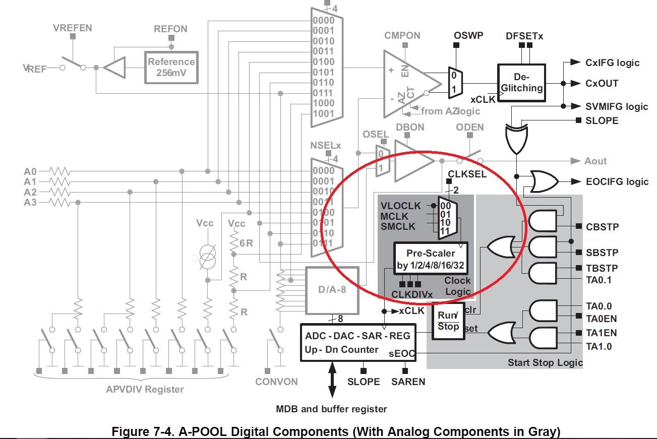
/****************************A_POOL ADC Conversion *******************************/
/* */
/* */
/* +----L092---+ */
/* |*1 14 | */
/* | 2 13 | */
/* | 3 12 | */
/* | 4 11 | */
/* | 5 10 | */
/* | 6 9 | */
/* | 7 8 | */
/* +-----------+ */
/* */
/* D.Dang/ D.Archbold/ D.Szmulewicz /F. Chen */
/* Texas Instruments Inc. */
/* Built with IAR Version 5.51.1 and CCS Verison 5.3.00090 */
/*********************************************************************************/
#include <msp430.h>
int Result;
volatile short int DegC;
int main(void)
{
WDTCTL = WDTPW + WDTHOLD; // Stop WDT
// Begin Configuration of the A-POOL registers
APCTL = 0; // Clear APCTL register
APIE |= EOCIE; // Enable Interrupt for End of Conversion
APTRIM = REFTSEL;
APVDIV = TMPSEN; // Enable Temperature Sensor
APCNF = CMPON+DBON+CONVON+APREFON+CLKSEL_MCLK; // Configure A-POOL elements, Select MCLK as A-POOL Clock Source
P1DIR |= (BIT4+BIT5+BIT6);
while(1)
{
APCTL = OSEL+ODEN+OSWP+APPSEL_4+APNSEL_5; // Set Channels and Start Conversion--+ODEN+
APINT = 0x00; // Clear ADC-DAC-REG
APIFG = 0;
APCTL |= CBSTP+SBSTP+RUNSTOP;
__bis_SR_register(LPM0_bits + GIE); // Enter LPM0 w/ interrupts enabled
Result = APINT;
DegC =(((Result-179)*125)/58) + 30; // Refer to datasheet for accuracy and offset specs
if(DegC>20){
P1OUT|=BIT4;
}
else{
P1OUT&=~BIT4;
}
__no_operation(); // SET BREAKPOINT HERE
}
}
//A_POOL Interrupt Service Routine
#if defined(__TI_COMPILER_VERSION__) || defined(__IAR_SYSTEMS_ICC__)
#pragma vector=APOOL_VECTOR
__interrupt void A_POOL(void)
#elif defined(__GNUC__)
void __attribute__ ((interrupt(APOOL_VECTOR))) A_POOL (void)
#else
#error Compiler not supported!
#endif
{
APIFG = 0; // Clear Interrupt Flag
__bic_SR_register_on_exit(LPM0_bits); // Exit Active to calculate Temperature
}
Please, Can someone give me an advice prevent this delay?
Thanks in advance