This thread has been locked.

If you have a related question, please click the "Ask a related question" button in the top right corner. The newly created question will be automatically linked to this question.

MSP430AFE253: MSP430AFE253 SD24 ADC error

Part Number: MSP430AFE253

My requirements: collecting AC 50Hz signals, wave 64 points per week, sampling rate of Fs=50*32=1600; MCLK=SCLK=12MHz
Timer clock frequency =MCLK; sampling timer timing length =12000000/1600=7500;
In the timer interrupt program, start the ADC conversion, and reverse the P1.3 pin status to monitor the timer length, to get the frequency output =800Hz, indicating that the timer is set correctly

void TIMER_A_INIT(void)
{  
  u16 t;
  //CCR0 = 7500; 
  t=12000000/(50*32);
  CCR0 = t;
  TACTL = TASSEL_2 + TACLR+ MC_1;
  CCTL0 = CCIE;
}

#pragma vector=TIMERA0_VECTOR
__interrupt void Timer_A (void)
{ 
      SD24CCTL0 |= SD24SC;
      P1OUT ^= BIT3;  ;
}


void sd24_a_init(void)
{
  u16 i;

  SD24CTL = SD24SSEL_1+SD24DIV_2+SD24XDIV_1+SD24REFON;    // 1.2V ref, SMCLK    Fadc=12000000/(4*3)=1000000
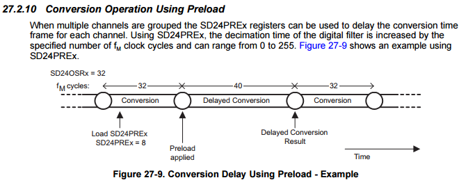
  SD24INCTL0 = SD24INCH_0+SD24GAIN_4+SD24INTDLY_3; // Interrupt on 1rd sample
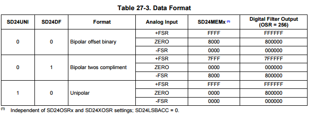
  SD24CCTL0  = SD24SNGL+SD24DF+SD24OSR_256+SD24IE; //单次转换模式,双极性模式补码输出,过采样256,,中断使能
  
  for (i = 0; i < 0x4000; i++);             // Delay for 1.2V ref startup
  index=0;
} 

#pragma vector=SD24_VECTOR
__interrupt void SD24AISR(void)
{   
   u8 i;
   if(SD24IV==SD24IV_SD24MEM0)
   {
      ad_buf[index] = SD24MEM0;      
      if (++index == samplebuftime) 
      {         
          for(i=0;i<samplebuftime;i++) ad[i]=ad_buf[i]; 
          index=0; 
      }  
      P1OUT ^= BIT4;
   }   
}

As set above, get the P1.4 pin output frequency =800 is correct. The sampling rate was 1600
But I read the AD sampling is wrong
Help me analyze where the problem is, thank you very much

  • Hi Alvin,

    Alvin Chen said:
    My requirements: collecting AC 50Hz signals, wave 64 points per week, sampling rate of Fs=50*32=1600; MCLK=SCLK=12MHz

    First, I'm not exactly sure how you calculated the sampling frequency (Fs), but I'll just assume you would like Fs to be 1600Hz. Keep in mind that this is your Fs (calculated), not Fs (actual).

    For the SD24_A, you set the actual sampling frequency Fs (actual) using the modulator frequency (Fm) divided by the oversampling rate (OSR). Thus, you've configured your Fm to be 1MHz and set OSR equal to 256, which makes Fs (actual) equal to 3906.25Hz (1MHz / 256).

    Alvin Chen said:
    As set above, get the P1.4 pin output frequency =800 is correct. The sampling rate was 1600
    But I read the AD sampling is wrong

    I'm not sure I completely understand this. Are you saying that your timer is configured properly but that you're getting samples from the SD24 that are different than you expected? I see that you're setting the "SD24DF" bit in the SD24CCTL0 register. Looking at Table 27-3 in the User's Guide, this makes the data format "bipolar twos compliment". Perhaps the results are correct but in a different format than expected.

    Regards,

    James

    MSP Customer Applications

  • I set the bipolar complement output, but all I read was negative, and the signals I gave were AC.
    What is the maximum frequency limit for ADC?
    Fadc=Fs (actual sampling rate) * oversampling rate *SD24INTDLY_x (number of delays)
  • Alvin Chen said:
    What is the maximum frequency limit for ADC?

    According to page 28 in the datasheet, the maximum input (modulator) frequency to the SD24_A module is 1.1MHz, whereas 1MHz is typical. Let's call this input frequency F(m).

    Alvin Chen said:
    Fadc=Fs (actual sampling rate) * oversampling rate *SD24INTDLY_x (number of delays)

    F(s) = F(m) / OSR

    In the time domain,

    t(conversion) = OSR / F(m)

    t(conversion) + t(delay) = ( OSR / F(m) ) + ( SD24PREx / F(m) ) = ( OSR + SD24PREx ) / F(m)

    You can learn more about this in Section 27.2.10 in the User's Guide. Also, the SD24INTDLY bits don't delay the conversion itself. These bits determine how many initial conversions (samples) are thrown away during the settling time to prevent wrong conversions. These bits are very different than the SD24PREx bits.

    Regards,

    James

    MSP Customer Applications

  •  please help me  check my Schematic.

  • Hello Alvin,

    Based on the configuration of the AFE for A0.0 in your schematic, it looks like you're measuring current with a single SD channel. If this is true, I'd strongly recommend referring to the schematic portion shown in Figure 4 (and Section 2.1.2.2) in the Single-Phase Electric Meter With Isolated Energy Measurement (Rev. A) User's Guide. In your schematic, you may want to replace R3 and R4 with inductors. Also, C1 and C2 may just need to be do-not-populate (DNP). More importantly, if you are using a current transformer (CT), then you'll want to add a burden resistor as shown in Figure 4. Also, I would recommend changing the values of C3, C4, and C5 to match those shown in Figure 4.

    If you want to use this channel to measure voltage, I'd recommend that you refer to Figure 3 (and Section 2.1.2.1) in the Single-Phase Electric Meter With Isolated Energy Measurement (Rev. A) User's Guide.

    Here's some additional feedback (based on the schematic for the TIDM-MSP430AFE253SUBMETEREVM board found here):

    1. Add at a 10uF capacitor and 0.1uF capacitor to AVCC.
    2. At 2.2nF, C6 is at the upper limit of recommended capacitance. Depending on your board's parasitic capacitance, you may need to reduce this value to 1nF or slow down the SBWTCK speed.
    3. I'm assuming that you're connecting DGND to AGND with a net-tie somewhere else in the schematic.

    Regards,

    James

    MSP Customer Applications

**Attention** This is a public forum