


Hardware:- (MP430FR5739) (LCD :- 1602a)
Software :- CCS 7.1
Problem :-
one (some time both lines) line of LCD display shows black boxes – I was struggling with this one.
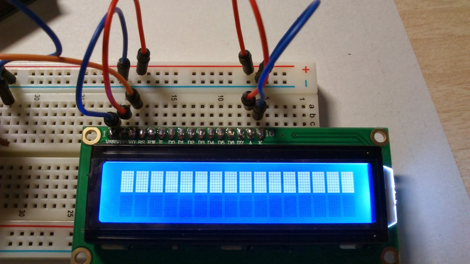
I checked my wiring Diagram many time It's 100% same to below diagram
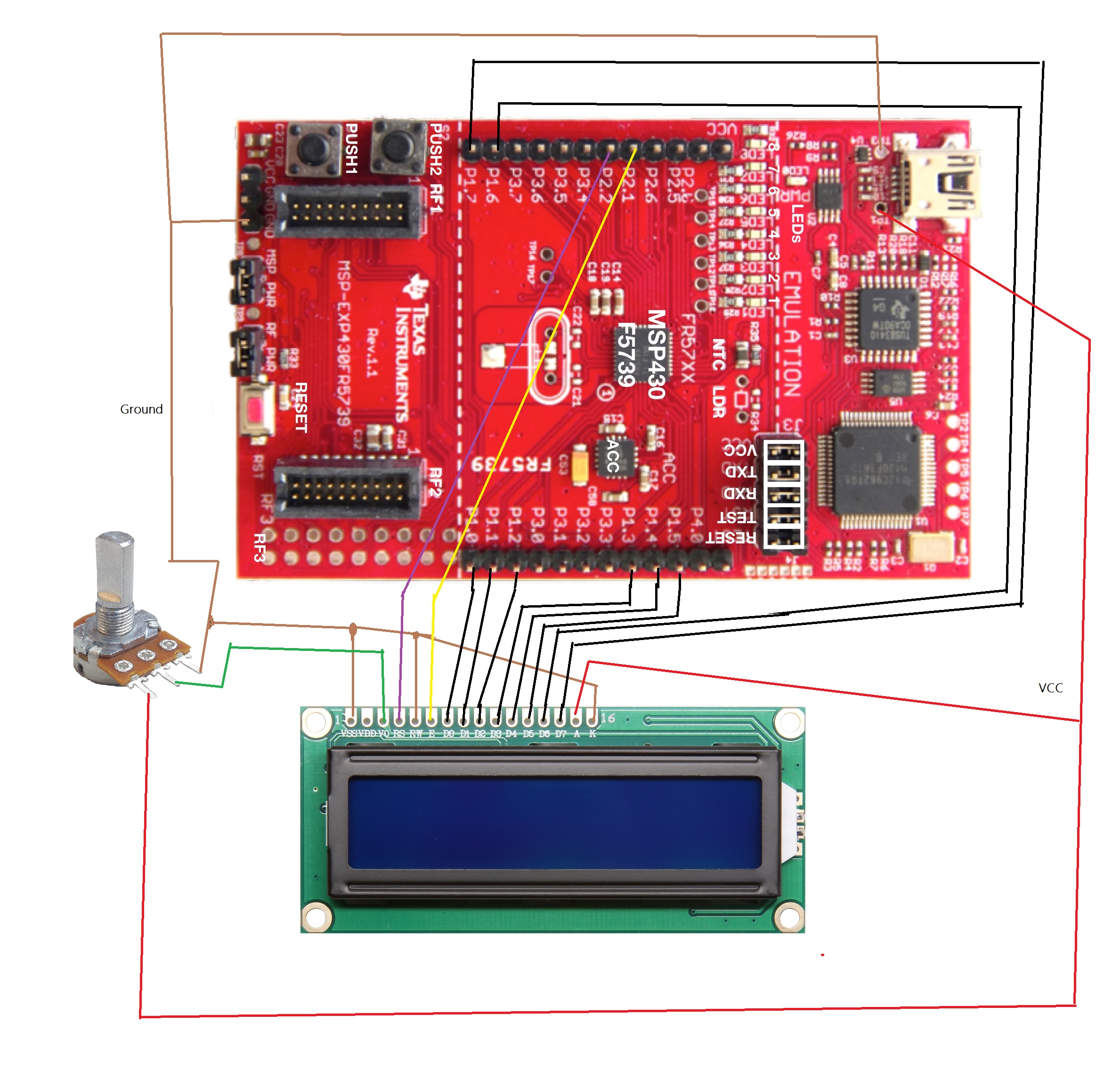
P1.0 => P1.7 (D0 to D7 Data line)
P2.2 => Enable
P2.1=> RS
V0 => pot middle (10K )
Vss and K => ground
Vdd and A = > +5v
also i tried to use external power supply but result was same.
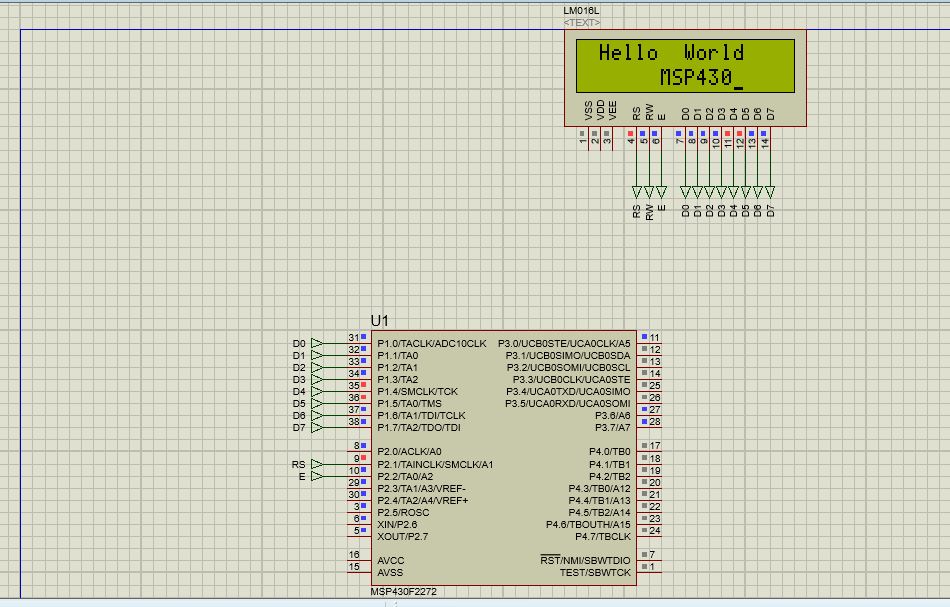
But is my simulation it's work fine.
Here is my code
#include "stdio.h"
#include "string.h"
#include "stdlib.h"
#define delay_value 500
void send_cmd(unsigned char command)
{
P1OUT &= 0X00;
P2OUT &= 0X00;
P1OUT = command;
P2OUT &= 0X00;
P2OUT &= ~BIT1; // RS = 0 for command, P1.6 0x40
//RW is grounded
P2OUT &= ~BIT2; //EN = 0, P1.7, 0x80
__delay_cycles(delay_value);
P2OUT |= BIT2; // EN = 1, P1.7, 0x80
__delay_cycles(delay_value);
P2OUT &= ~BIT2; //EN = 0, P1.7, 0x80
__delay_cycles(delay_value);
}
void send_char(unsigned char character)
{
P1OUT &= 0X00;
P2OUT &= 0X00;
P1OUT = character;
// P1OUT &= 0x00;
P2OUT |= BIT1; // RS = 0 for command, P1.6
// RW is grounded
P2OUT &= ~BIT2; //EN = 0, P1.7
__delay_cycles(delay_value);
P2OUT |= BIT2; // EN = 1, P1.7
__delay_cycles(delay_value);
P2OUT &= ~BIT2; //EN = 0, P1.7
__delay_cycles(delay_value);
}
void send_string(char *String)
{
unsigned char i=0;
while(String[i]!='\0')
{
P1OUT &= 0X00;
P2OUT &= 0X00;
P1OUT = String[i];
P2OUT |= BIT1; // RS = 0 for command, P1.6
// RW is grounded
P2OUT &= ~BIT2; //EN = 0, P1.7
__delay_cycles(delay_value);
P2OUT |= BIT2; // EN = 1, P1.7
__delay_cycles(delay_value);
P2OUT &= ~BIT2; //EN = 0, P1.7
__delay_cycles(delay_value);
if(i>=16) // If the number of characters in the string > 16, then the below command automatically
send_cmd(0x18); // Shift the display right side
__delay_cycles(40000); // 100 millisec delay
i++;
}
}
void LCD_Init(void)
{
send_cmd(0x38); // configure LCD as 2 lined 5x7 matrix
__delay_cycles(delay_value);
send_cmd(0x0E); //display on, cursor blink
__delay_cycles(delay_value);
send_cmd(0x06); // auto increment of cursor
__delay_cycles(delay_value);
send_cmd(0x01); // clear display
__delay_cycles(delay_value);
}
void main(void)
{
WDTCTL = WDTPW + WDTHOLD; // Stop WDT
BCSCTL1 = CALBC1_1MHZ; // Set DCO
DCOCTL = CALDCO_1MHZ;
BCSCTL2 &= ~(DIVS_3); //This line of code ensures that the SMCLK divider is 0,
// so we have SMCLK=DCO=1MHz (in fact if we are to have a /8 divider, it should be BCSCTL2 |= DIVS_3;).
P1DIR = 0xFF; // make P1 as output
P2DIR = 0xFF; // make P2 as output
P1SEL = 0; // These two are "Function Select Registers PxSEL and PxSEL2",
P1SEL = 0; // If both are zero's means simple I/O function is selected.
//P2SEL2 = 0; // If both are zero's means simple I/O function is selected.
P2DIR |= 0x01; // Set P1.0 to output direction
P2REN |= 0x01;
__delay_cycles(1500); // wait for more than 15ms after supply rises to 4.5V
send_cmd(0x30);
__delay_cycles(400); // wait more than 4.1ms
send_cmd(0x30);
__delay_cycles(100); // wait more than 100us, but __delay_cycles(1) will provide 1ms
send_cmd(0x30);
__delay_cycles(100);
send_cmd(0x02); // return to home
__delay_cycles(100);
LCD_Init(); // LCD initialization
while(1)
{
send_cmd(0x01); // clear display
__delay_cycles(delay_value);
send_cmd(0x81); // clear display
__delay_cycles(delay_value);
send_string("Hello World");
__delay_cycles(delay_value);
send_cmd(0xC0); // clear display
__delay_cycles(delay_value);
send_string(" MSP430");
__delay_cycles(1000000);
}
}
Also i tried with some other codes. but the result was same.
please help me if you can.
Thank you.
Have a nice day.

