hello,
I am using msp430f5659 and trying to interface uart. I am not able to transmit any char. My Ucs code is:
void clock()
{
UCSCTL3 |= SELREF_2; // Set DCO FLL reference = REFO
UCSCTL4 |= SELA_2; // Set ACLK = REFO
__bis_SR_register(SCG0); // Disable the FLL control loop
UCSCTL0 = 0x0000; // Set lowest possible DCOx, MODx
UCSCTL1 = DCORSEL_4; // Select DCO range 8MHz operation
UCSCTL2 = FLLD_1 + 121; // Set DCO Multiplier for 4MHz
// (N + 1) * FLLRef = Fdco
// (121 + 1) * 32768 = 4 MHz
// Set FLL Div = fDCOCLK/2
__bic_SR_register(SCG0); // Enable the FLL control loop
// Worst-case settling time for the DCO when the DCO range bits have been
// changed is n x 32 x 32 x f_MCLK / f_FLL_reference. See UCS chapter in 5xx
// UG for optimization.
// 32 x 32 x 4 MHz / 32,768 Hz = 125000 = MCLK cycles for DCO to settle
__delay_cycles(125000);//
// Loop until XT1,XT2 & DCO fault flag is cleared
do
{
UCSCTL7 &= ~(XT2OFFG + XT1LFOFFG + DCOFFG);
// Clear XT2,XT1,DCO fault flags
SFRIFG1 &= ~OFIFG; // Clear fault flags
}while (SFRIFG1&OFIFG); // Test oscillator fault flag
}
and Uart init code is :
void uart(){
P9SEL |= RXD + TXD ; // Assign TX AND RX FACILITY FOR P9.2 AND P9.3 respectively
UCA2CTL1 |=UCSWRST;
UCA2CTL1 |= UCSSEL__ACLK; // SELECT SMCLK 1 MHZ clock source to USCI module
UCA2CTL0 = 0x00; // no parity, 8 bit mode, lsb first, UART Async mode, stop bit=1
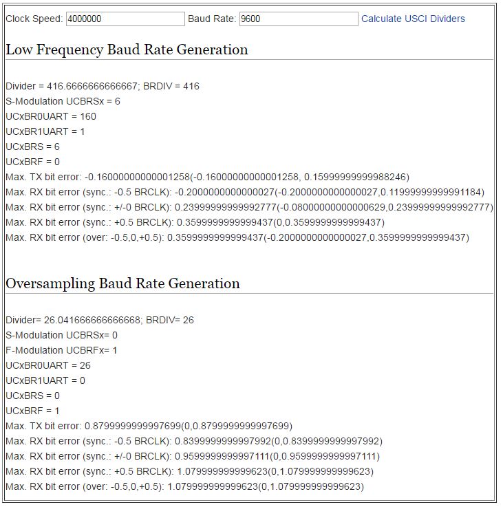
UCA2BR0=416; // presacalar value for BAUD rate generator 9600 bps
UCA2BR1=0;
UCA2MCTL=UCBRS_5 + UCBRF_0; // Modulation UCBRSx=5, UCBRFx=0
UCA2CTL1 &=~UCSWRST; //initialize USCI state machine
UCA2IE |= UCRXIE; // Enable USCI_A0 RX interrupt
__bis_SR_register(GIE); // global interrupt enable
}
I am not able to identify where is the problem.