This thread has been locked.

If you have a related question, please click the "Ask a related question" button in the top right corner. The newly created question will be automatically linked to this question.

MSP430FR2633: Interpreting sensor/cycle packets.

Part Number: MSP430FR2633
Other Parts Discussed in Thread: CAPTIVATE-BSWP, MSP-EXP430FR2311

Hi,


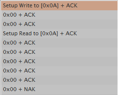
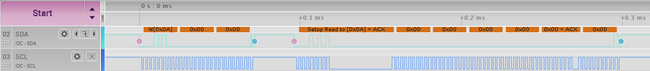
I am trying to read proximity sensor packets from MSP430FR2633 MCU via I2C (bulk) interface. The slave address I'm using is 0x0A. So, the master (host) sends the following sequence:

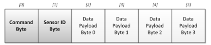
[0x00][0x01]  (first byte 0x00 corresponds to command id and second byte 0x01 to sensor id [of the proximity sensor]).

I use the i2c helper functions in i2cbsl.c. Thus, for the above I do as follows:

uint8_t writeBuffer[2] = {0x00, 0x01};

uint8_t readBuffer[100];

MSP430BSL_I2CWriteRead(writeBuffer, 2, readBuffer, 8);

Although I get some data in the readBuffer, it does not look as expected. For example, the first and second bytes in the readBuffer are not 0x00 and 0x01. The following is the sequence I get:

18 01 00 00 00 00 00 f9
18 01 00 01 00 00 00 f8
08 00 00 00 00 00 00 00
0c 01 01 00 00 00 00 0e
08 00 01 00 00 00 00 01
18 01 02 00 00 00 00 45
08 00 02 ff ff 00 00 00
14 01 03 00 00 00 00 f0
08 00 03 ff ff 00 00 01

... repeats many times....

Could you help me understand what is going on? Any tips/information on debugging is most welcome. Is there documentation (other than CapTIvate technology guide) that I can refer to regarding how to interpret the various packets (sensor, cycle, general purpose etc.).

Thanks,

Santhosh.

  • Hello,

    I don't think you want to use the "MSP430BSL_I2CWriteRead()" command for communicating with a sensor over a typical I2C interface. The BSL interface is used to program the MSP430FR2633 through an I2C interface versus the typical JTAG (4-wire or 2-wire SBW) interfaces. I'm assuming that the MSP430FR2633 is the host and the sensor is the slave.

    I would recommend looking at our I2C code examples.

    Regards,

    James

    MSP Customer Applications
  • Another good reference is Section 5 Common I2C Communication Issues in the Solutions to Common eUSCI and USCI Serial Communication Issues on MSP430™ MCUs app note.

    Regards,

    James

    MSP Customer Applications

  • Also, if you're not already aware of them, here's a link to the code examples for the MSP430FR2633.

    There are four I2C examples that should be very helpful references:

    • msp430fr243x_euscib0_i2c_10.c
    • msp430fr243x_euscib0_i2c_11.c
    • msp430fr243x_euscib0_i2c_15.c
    • msp430fr243x_euscib0_i2c_16.c

    Regards,

    James

    MSP Customer Applications

  • Hi James,

    Thank you for your response. In my case the host is a dual-core ARM cortex A9 and the slave is the MSP430FR2633. We are using the MSP CapTIvate development kit (ref: www.ti.com/.../msp-capt-fr2633) where we bypass the programmer card and directly connect the MSP dev card to our ARM dev card using the I2C interface. So, basically our setup looks like this:

    [ARM A9 I2C Master]<--I2C-->[MSP430FR2633]<=48 pin connector =>[Captivate BSWP]

    Note: I am able to program the MSP430FR2633 MCU using the BSL sequence from the Host CPU using I2C slave address 0x80. However, in the case of reading sensor packets, I still manage to receive the data through the I2C interface (as mentioned in my original post) but I'm unable to interpret the result of the reads.
    Thus, my question is whether the sequence I send [0x00 0x01] is incorrect (or perhaps something is amiss)? Is there a particular order in which the master should read packets from the slave?

    Thanks,
    Santhosh
  • Hi again,

    I'm attaching a logic-analyzer screenshot that shows the sequence where 0x00 and 0x01 are written to address 0x0A and also a read request being sent. In the screenshot, channel 0 corresponds to SCL, channel 1 to SDA and channel 2 to IRQ (i.e., from the slave to master).

    Regards,
    Santhosh

  • Hello Santhosh,

    Thank you for your detailed reply. It is very informative into what you're observing and what your system looks like.

    I suspect that you've programmed the MSP430FR2633 with the demo code. Thus, the communication that you're observing is the protocol used between the device and the CapTIvate Design Center GUI on a PC. While all these packets do contain valuable information, it's like drinking from a fire hose unnecessarily. The Design Center GUI requires this much data, but in your application, your host processor only need information like "this button turned on", "motion was detected", etc.

    Thus, I'd recommend taking a look at the Software Library portion of the CapTIvate Technology Guide. For example, there's a starter application discussed called 'main.c'. Basically, this code would run on the MSP430FR2633 and would turn on LED2 when motion is detected by a sensor. For something like your application, you'd have to add code that would send a message over I2C to the host processor based on some type of input (motion, button press, etc.). Simple call-back functions are associated with each sensor.

    void my_button_callback(tSensor* pSensor)
    {
        if((pSensor->bSensorTouch == true) && (pSensor->bSensorPrevTouch == false))
        {
            // BUTTON PRESSED
            // DO SOMETHING ...
        }
        else if((pSensor->bSensorTouch == false) && (pSensor->bSensorPrevTouch == true))
        {
            // BUTTON RELEASED
            // DO SOMETHING ...
        }
    }

    Does this make sense?

    If you need to implement something more advanced and are required to use the CapTIvate protocol, we can continue our discussion and dig deeper. Use cases for the protocol (copied from the "Software Library" -> "Communications Module" -> "Protocol Layer" section in the CapTIvate Technology Guide) include the following:

    1. Capacitive Touch Development and Tuning Capacitive touch development and tuning involves looking at real-time data from a touch panel and adjusting software parameters to achieve the desired response and feel from the sensors on that panel. For example: tuning a capacitive button involves looking at the raw data coming back from the microcontroller about that button, and adjusting thresholds, de-bounce, and filters accordingly to create a robust user interface. Having the ability to adjust all of these software parameters in real-time while looking at sensor data, without re-compiling code, is extremely powerful and reduces development time. The Captivate protocol was designed with the Captivate Design Center specifically to meet this need.
    2. Interface to Host Processor Most capacitive touch user interfaces involve a dedicated microcontroller driving the touch panel, which communicates up to a host processor of some kind. The flexibility of the Captivate protocol allows for it to be re-used as an interface to a host processor; it can stream touch status, proximity status, and slider/wheel position up to a host.
    3. In-Field / In-System Debug Interface and Tuning Since the Captivate protocol supports reading and writing of capacitive touch tuning parameters, as well as the streaming of real-time data, it could potentially be utilized as a diagnostic tool in the field when coupled with the Captivate Design Center PC tool.

    Regards,

    James

    MSP Customer Applications

  • Also, for more details about the sensor, cycle, trackpad, general purpose, and parameter packets, take a look at the "Software Library" -> "Communications Module" -> "Protocol Layer" -> "Introduction to Packet Types" section in the CapTIvate Technology Guide for more information.

    Hopefully this helps.

    Regards,

    James

    MSP Customer Applications
  • Hi James,

    Thank you for your reply. I will try out the top level software library and the callback functions as you suggested.

    Regards,

    Santhosh

  • That sounds good. If you have any questions, don't hesitate to let me know.

    Regards,

    James

    MSP Customer Applications
  • Hi James,

    Thank you for the help before. I am now able to read the sensor packets successfully. However, I have a new question:
    I am trying to read various parameters (such as lta filter beta, negative touch threshold etc.) by sending a "parameter packet" as described in the CapTIvate user guide under Protocol layer->Parameter packets. I am using the default i2c slave address 0x0A. However, I do not get any ACK from the device. I suspect it may be due to the fact that this part is not implemented in the MSP430 code (generated using the graphical design UI).
    My question is whether this is the case, and also whether an implementation of parameter packet transmission exists somewhere that I may download?

    Thanks,
    Santhosh
  • Hi again,

    I suppose it may be due to the fact that MSP430 sw expects the parameter packet to be of the format "tParameterPacket" (i.e., to include sync, blank, length and checksum at the end) and I send the packet as described in the document [cmd byte][rw][sensor_id][][][][]?

    Regards,
    Santhosh
  • Hello Santhosh,

    Option 1) At a high level, you don't really need to use the same protocol that's used by the CapTIvate Design Center. You can implement a simple protocol based on the I2C interface between the host and the MSP430FR2633 (slave). Based on the number of sensors and required measurements/data/results, you can come up with a set number of commands. Then, when the host processor sends the MSP430FR2633 (slave) that command, the slave will then send the appropriate number of bytes based on the received command. You can utilize the call-back functions to obtain the sensor data, but you'd have to implement the I2C protocol on the MSP430FR2633.

    Option 2) An alternative option that may be more challenging up front but then easier to use would be to utilize the I2C driver used with the CapTIvate Design Center. This way, you can take advantage of using the parameter packets that are described in the Design Guide. Let me try to walk you through this.

    These steps assume that you already have a CapTIvate Design Center project for your design, and that the sensors in your design have been tuned. Basically, you'll want to set up your CapTIvate project for REGISTER I2C, which will allow you to read packets from your host processor. Since you're using the MSP430FR2633 and the CAPTIVATE-BSWP panel, we'll use that as the slave.

    Setting up the target (slave) MCU

    Step 1

    To enable REGISTER I2C communication, open the CapTIvate Design Center Controller Customizer (double-click the MSP430 icon on the canvas). Then, select "REGISTERI2C" as the communication interface.

    Step 2

    You'll need to update your source code now to include this change by selecting "Generate Source Code" in the Controller Customizer window. Next, browse to your CCS project root directory.

    Step 3

    Basically, this change has modified one of the header files, so re-build your CCS project containing the update.

    Step 4

    Re-program the CapTIvate target MCU, the MSP430FR2633, with the updated project. Finally, terminate any debug sessions. That's it. The CapTIvate Software Library will take care of everything else.

    Making I2C Connections

    You've already connected the host processor to the target MCU and have the proper I2C pull-ups.

    Starting REGISTERI2C Communication

    For this example, let's assume that the MSP43FR2311 acts as the host processor. It can be programmed with MSP Driver Library software and the I2C Master driver used in CapTIvate examples for controlling the DRV26xx haptic actuators. A basic loop may be constructed as shown below to read data from the CapTIvate target device, the MSP430FR2633.

    The I2C master driver calls shown here should be easy to translate to whichever host driver is being used in an end application. The I2CTOOLS utility on an embedded Linux host may be used in a similar fashion to perform writes to and reads from the I2C bus.

    In this basic example, the sensor packet for sensor 0x00 was read. The first bit of the 6th (final) byte of the received data is used to turn on and of P1.0 on the MSP-EXP430FR2311 LaunchPad, which controls an LED. That bit in the received data corresponds to the global touch flag for the sensor with ID 0x00. This means that any touch on sensor 0 will cause the LED to illuminate. Sensor ID 0x00 corresponds to the button group sensor when using the CAPTIVATE-BSWP demo.

    void loop(void)
    {
         static uint8_t tx[16];
         static uint8_t rx[16];
         if (capture==true)
         {
              capture = false;
    
              tx[0] = 0x00;
              tx[1] = 0x00;
              I2CMaster_writeBuffer(0x0A, &tx[0], 2);
              I2CMaster_readBuffer(0x0A, &rx[0], 6);
    
              if (rx[5] & BIT0)
              {
                   P1OUT |= BIT0;
              }
              else
              {
                   P1OUT &= ~BIT0;
              }
         }
    }

    We're currently working on some collateral that will describe how to do this and other things, but unfortunately they haven't been released yet. Hopefully this helps, but please let me know if you aren't able to get the packet data by following these guidelines.

    Regards,

    James

    MSP Customer Applications

  • Hi James,


    Thank you for a very informative answer. I will try out option 2 first (as I would be able to use the I2C driver that's already present). If it turns out to be tricky, I'll try option 1 too.

    Best regards,

    Santhosh

  • Hi James,

    I tried option 1 (i.e., register i2c mode). I was able to send a parameter read request command and receive a response. However, all the bits in the data were 0. I sent various commands and got back just 0s as shown below:

    55 aa 03 8d 00 00 00 00 00 00 00 00
    55 aa 03 82 00 00 00 00 00 00 00 00
    55 aa 03 84 00 00 00 00 00 00 00 00
    55 aa 03 85 00 00 00 00 00 00 00 00
    55 aa 03 86 00 00 00 00 00 00 00 00
    55 aa 03 87 00 00 00 00 00 00 00 00
    55 aa 03 88 00 00 00 00 00 00 00 00
    55 aa 03 89 00 00 00 00 00 00 00 00
    55 aa 03 8a 00 00 00 00 00 00 00 00
    55 aa 03 8b 00 00 00 00 00 00 00 00
    55 aa 03 8c 00 00 00 00 00 00 00 00
    55 aa 03 9b 00 00 00 00 00 00 00 00

    Parameter Value
    Runtime recalibration enable False
    Proximity threshold 0
    Prox. debounce in threshold 0
    Prox. debounce out threshold 0
    Touch debounce in threshold 0
    Touch debounce out threshold 0
    Sensor timeout threshold 0
    Count filter enable False
    Count filter beta 0
    LTA filter beta 0
    Negative touch threshold 0

    Furthermore, I tried to write and read a parameter packet in the MSP430 (CAPT_appStart function). The code snippet I used is shown below. The result was the same; I just got a bunch of 0s.
    tTLParameterAccessResult actionAfterParamterAccess;
    uint8_t cmdBuffer[] = {0x55,0xAA,0x03,0x80,0x01,0x00,0x00,0x01,0x00,0x00,0x82,0x00};
    actionAfterParamterAccess = MAP_CAPT_accessSensorParameter(
    g_uiApp.pSensorList,
    (tParameterPacket*)cmdBuffer
    );
    cmdBuffer[4] = 0;
    cmdBuffer[7] = 0;
    cmdBuffer[10] = 0x80;
    actionAfterParamterAccess = MAP_CAPT_accessSensorParameter(
    g_uiApp.pSensorList,
    (tParameterPacket*)cmdBuffer
    );

    I wonder why this happens?

    Best regards,
    Santhosh
  • Hi James,

    I wonder if you have any updates on this thread?

    Thanks,
    Santhosh
  • Hi Santhosh,

    When using REGISTER_I2C mode, the packet headers are not needed/used.  Meaning, you don't need the SYNC, BLANK, and LEN bytes when you request a parameter on the host side.  This is probably what the problem is at this point.  When in REGISTER_I2C mode, the CapTIvate Software Library looks at the first byte it receives and interprets this as the CMD ID.  In your test case, it would be attempting to interpret 0x55 as a CMD.  Since it doesn't recognize 0x55, it will just return 0x00's.  For example, to request the sensor packet (CMD ID 0x00) of sensor 0 (SENSOR ID 0x00), you would simply write 0x00 0x00, and read out the 6 bytes of the sensor packet.

    Make note of the following important things from this example:

    1. The master (host) requested a sensor packet by writing the first two bytes of the sensor packet it wanted. The first two bytes indicate to the slave device what data to fetch for the host. Sensor packets are fixed length packets (always 6 bytes) that indicate the general status of a sensor. For button sensors, this includes information such as the dominant button that is being touched. For slider and wheel sensors, this includes the calculated slider/wheel position. Review the CapTIvate Protocol Sensor Packet description for details on the packet structure. The basic format is shown below:


      The first two bytes (shaded darker) include the CMD byte and the Sensor ID byte. The CMD byte tells the slave to fetch a sensor packet. The command ID for a sensor packet is 0x00. The Sensor ID byte tells the slave which sensor to fetch the packet for. In this case, we asked for Sensor ID 0x00, which corresponds to the button group sensor. These are the two items that are needed for reading a sensor packet.
    2. Following the host requesting the packet, the host performs a read of the data to retrieve the entire packet that was generated by the slave (CapTIvate) device. This means that all 6 bytes of the sensor packet are read out of the device. Note that the two request bytes (the CMD byte and sensor ID byte) are re-sent back to the host. This is done as a confirmation to the host that the correct data was retrieved. The protocol specification states that payload byte 3 (the last byte of the packet) contains the sensor status byte. This indicates global touch/prox/detect status, global previous touch status, and other global diagnostic information. The protocol specification also states that the first byte (byte 0) contains the dominant element that is being touched in the button group. This information may be used to extract the ID of the button that is being touched the most in the group.
    3. Note that the host may poll the slave device at any time, regardless of where the CapTIvate MCU is in the process of running a conversion. Often times it may be ideal to read out data when a new sample is available. For this purpose, a digital GPIO pin may be used between the slave and host as a means for the slave to indicate to the host that it wants its attention. This is left up to the user to implement, since different applications have different requirements. Some systems may want the host to be flagged whenever new data is available; others may only want the host to be flagged if someone is near the panel. Still, others may only want the host flagged when a confirmed touch is detected.

    Give this a try on the host side and let me know if that fixes the issue for you.

    Regards,

    Walter

  • Hello Santhosh,

    Did Walter's recommendations resolve your issue?

    Regards,

    James

    MSP Customer Applications
  • Hi Walter and James,

    Thank you for your reply. I did try Walter's recommendation, but the response I get looks completely weird. The command I send is 3 bytes long : [command id] [0] [sensor id] and I read 7 bytes back. Please find below the response I got for the same set of parameters that I posted earlier.

    00 00 01 00 8e 00 00
    00 00 00 00 00 00 00
    00 00 00 00 00 00 00
    00 00 ff ff ff ff ff
    ff ff ff ff ff ff ff
    ff ff ff ff ff ff ff
    ff ff ff ff ff ff ff
    ff ff ff ff ff ff ff
    ff ff ff ff ff ff ff
    ff ff ff ff ff ff ff
    ff ff ff ff ff ff ff
    ff ff ff ff ff ff ff

    In addition, I found that the I2C communication completely stops and the bus appears to be hung.

    Best regards,
    Santhosh
  • Hi Santhosh,

    Can you clarify which bytes in the capture above are read vs. write and where the I2C start/stop conditions are?

    Walter

  • Hi Walter,

    The bytes written to the slave address 0x0A are: [command byte] [read/writen = 0] [sensor id = 0] (basically 3 bytes sent in that order), and then I read 7 bytes from the same slave address immediately. The hex output I pasted is what I obtained for various command bytes (same order as in an earlier reply from me starting with "runtime recalibration enable" up to "negative touch threshold").

    I'm afraid I will not be able to test further at the moment as I am on vacation. I will be back in office in a couple of weeks' time and then I would be able to resume testing.

    Best regards,
    Santhosh

**Attention** This is a public forum