Other Parts Discussed in Thread: MSP430G2553
Tool/software: Code Composer Studio
Hi,
I want to control four daisy chained SPI slaves with the MSP430 (the master device). I have several issues doing this:
1. I want the SPI clk rate to be 16 MHz, the maximum clk frequency of my microcontroller. Here is what I do:
BCSCTL1  = CALBC1_16MHZ;                             	// Set range to 16MHz
DCOCTL   = CALDCO_16MHZ;                             	// Set DCO step and modulation to 16MHz

UCA0BR0 |= 0x01;					//baud rate
UCA0BR1 = 0;
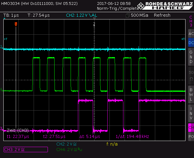
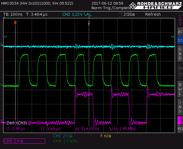
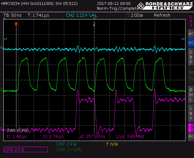
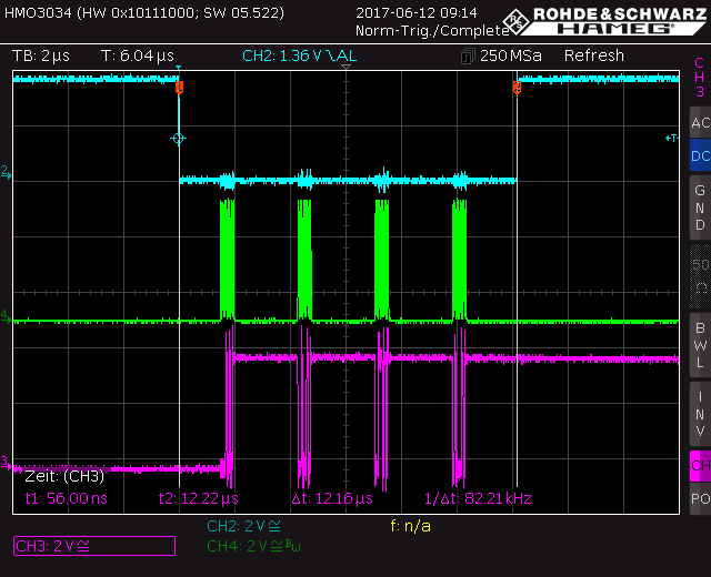
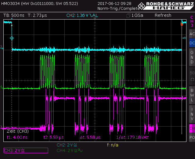
When I set the clk rate to 16MHz, and observe the Din and SCLK signal generated by MSP430, it looks almost like a sine wave (the rise time is really slow). When I slow down the clk to 1 MHZ, the two signals look fine. I want to run the SPI clk at 16 MHz. How can I do that without compromising the signal integrity?
2. Each slave device has 8 switches, so for four devices, I need to send 32 bits to slave one. The bits should then travel through the shift registers to get to the last device.I do not know how to do this. I am sending 8 bits as follows:
P1OUT &= ~0x02;                                                                 //select device
if (IFG2 & UCA0TXIFG) 								//if USCI_A0 TX buffer ready
  {
     UCA0TXBUF = 0x2D; 								//send data over SPI to slave

  }

if (IFG2 & UCA0RXIFG); 							        // if USCI_A0 RX Received
  {
     received_ch = UCA0RXBUF; 							// Store received data
     P1OUT |= 0x02;								//unselect device, update switches
  }
Can anyone tell me how to do this?
Here is the entire code for your reference:
#include "msp430G2553.h"


volatile char received_ch = 0;
int main(void) {

	  WDTCTL   = (WDTPW | WDTHOLD);                       	// Stop watchdog timer

	  BCSCTL1  = CALBC1_16MHZ;                             	// Set range to 16MHz
	  DCOCTL   = CALDCO_16MHZ;                             	// Set DCO step and modulation to 16MHz

	  P1OUT    &= ~0x02;                           			// Chip select (P1.1)
	  P1DIR    |= 0x02;                                    	// Set the pins to output direction
	  P1SEL    = 0x14;                                   	// Set special function to timer module (P1.4-->Sclk, P1.2-->DIN)
	  P1SEL2   = 0x14;										//Universal serial communication
	  UCA0CTL1 = UCSWRST;									//put the module in reset mode to set up operations
	  UCA0CTL0 |= UCCKPH + UCMSB + UCMST + UCSYNC; 			//3-pin, 8-bit SPI master
	  UCA0CTL1 |= UCSSEL_2;									//SMCLK
	  UCA0BR0 |= 0x01;										//baud rate
	  UCA0BR1 = 0;
	  UCA0MCTL = 0; 										//no modulation, should be cleared when using SPI mode
	  UCA0CTL1 &= ~UCSWRST; 								//initialize USCI state machine

	  IE2 |= UCA0TXIE; 										//Enable USCI0 TX interrupt
	  _BIS_SR(GIE);                                  		// Enable global interrupts

	  while( 1 );                                         	// Endless loop
	}

#pragma vector=USCIAB0TX_VECTOR
__interrupt void USCI0TX_ISR(void)
{
	P1OUT &= ~0x02; 										//Sync not is active low. When low, DIN and shift registers are enabled, when high data is updated.

	if (IFG2 & UCA0TXIFG) 									//if USCI_A0 TX buffer ready
		{
		UCA0TXBUF = 0x2D; 									//send data over SPI to slave
		}

		if ((IFG2 & UCA0RXIFG)); 							// if USCI_A0 RX Received
		{
		received_ch = UCA0RXBUF; 							// Store received data

		P1OUT |= 0x02;										//unselect device, update switches
		}
 }