- Ask a related questionWhat is a related question?A related question is a question created from another question. When the related question is created, it will be automatically linked to the original question.


Part Number: MSP432P401R
Tool/software: Code Composer Studio
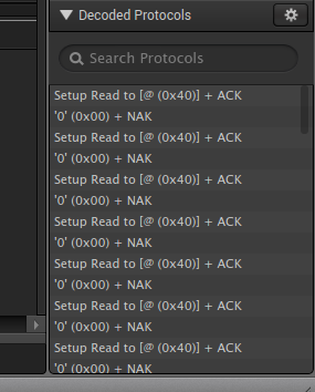
Need a little help understanding why my interrupts are being disabled when I change mode to receive. Prior to this step all the interrupts are enabled. After stepping through this line, they all disable. Please see hightlighted line and full code shown below.
Thanks
if (status & EUSCI_B_I2C_TRANSMIT_INTERRUPT0)
{
while (TxByteCtr)
{
UCB0TXBUF = TXData;
//UCB0IFG &= ~(UCTXIFG0);
TxByteCtr--;
//MAP_Interrupt_disableSleepOnIsrExit();
}
UCB0IE |= UCRXIE0;
UCB0CTLW0 |= ~(UCTR); This line of code is disabling all of my interrupts and not allowing the RXIFG to be set after the restart is sent.
UCB0CTLW0 |= UCTXSTT;
#include "driverlib.h"
/* Standard Defines */
#include <stdint.h>
#include <stdbool.h>
#include <string.h>
#include <Si7051.h>
/* Slave Address for I2C Slave */
#define SLAVE_ADDRESS IC_ADDRESS_TMP7051_ADDRESS
#define NUM_OF_REC_BYTES 2
/* Variables */
const uint8_t TXData = {0xE3};
static uint8_t RXData[NUM_OF_REC_BYTES];
static uint8_t RxByteCtr, TxByteCtr;
static volatile uint32_t xferIndex;
static volatile bool stopSent ;
/* I2C Master Configuration Parameter */
const eUSCI_I2C_MasterConfig i2cConfig =
{
EUSCI_B_I2C_CLOCKSOURCE_SMCLK, // SMCLK Clock Source
3000000, // SMCLK = 3MHz
EUSCI_B_I2C_SET_DATA_RATE_100KBPS, // Desired I2C Clock of 100khz
0, // No byte counter threshold
EUSCI_B_I2C_NO_AUTO_STOP // No Autostop
//EUSCI_B_I2C_SEND_STOP_AUTOMATICALLY_ON_BYTECOUNT_THRESHOLD
};
int main(void)
{
static volatile uint32_t ii;
/* Disabling the Watchdog */
MAP_WDT_A_holdTimer();
/* Select Port 1 for I2C - Set Pin 6, 7 to input Primary Module Function,
* (UCB0SIMO/UCB0SDA, UCB0SOMI/UCB0SCL).
*/
MAP_GPIO_setAsPeripheralModuleFunctionInputPin(GPIO_PORT_P1,
GPIO_PIN6 + GPIO_PIN7, GPIO_PRIMARY_MODULE_FUNCTION);
//stopSent = false;
memset(RXData, 0x00, NUM_OF_REC_BYTES);
/* Initializing I2C Master to SMCLK at 100khz with no autostop */
MAP_I2C_initMaster(EUSCI_B0_BASE, &i2cConfig);
/* Specify slave address */
MAP_I2C_setSlaveAddress(EUSCI_B0_BASE, SLAVE_ADDRESS);
/* Set Master in transmit mode */
MAP_I2C_setMode(EUSCI_B0_BASE, EUSCI_B_I2C_TRANSMIT_MODE);
/* Enable I2C Module to start operations */
MAP_I2C_enableModule(EUSCI_B0_BASE);
/* Enable and clear the interrupt flag */
MAP_I2C_clearInterruptFlag(EUSCI_B0_BASE, EUSCI_B_I2C_RECEIVE_INTERRUPT0);
MAP_I2C_clearInterruptFlag(EUSCI_B0_BASE, EUSCI_B_I2C_NAK_INTERRUPT);
MAP_I2C_clearInterruptFlag(EUSCI_B0_BASE, EUSCI_B_I2C_TRANSMIT_INTERRUPT0);
//Enable master Transmit interrupt
MAP_I2C_enableInterrupt(EUSCI_B0_BASE, EUSCI_B_I2C_NAK_INTERRUPT);
MAP_I2C_enableInterrupt(EUSCI_B0_BASE, EUSCI_B_I2C_RECEIVE_INTERRUPT0);
MAP_I2C_enableInterrupt(EUSCI_B0_BASE, EUSCI_B_I2C_TRANSMIT_INTERRUPT0);
//MAP_Interrupt_enableSleepOnIsrExit();
MAP_Interrupt_enableInterrupt(INT_EUSCIB0);
while (1)
{
//for (ii = 4000; ii > 0; ii--);
RxByteCtr = 2;
TxByteCtr = 1;
while (MAP_I2C_masterIsStopSent(EUSCI_B0_BASE) == EUSCI_B_I2C_SENDING_STOP);
UCB0TXBUF = TXData;
UCB0CTLW0 |= UCTR + UCTXSTT;
MAP_PCM_gotoLPM0InterruptSafe();
}
}
/*******************************************************************************
* eUSCIB0 ISR. The repeated start and transmit/receive operations happen
* within this ISR.
*******************************************************************************/
void EUSCIB0_IRQHandler(void)
{
uint_fast16_t status;
status = MAP_I2C_getEnabledInterruptStatus(EUSCI_B0_BASE);
if (status & EUSCI_B_I2C_STOP_INTERRUPT)
{
UCB0IFG &= ~(UCSTPIFG);
}
if (status & EUSCI_B_I2C_NAK_INTERRUPT)
{
//MAP_Interrupt_disableSleepOnIsrExit();
UCB0IFG &= ~(UCNACKIFG);
UCB1CTLW0 |= UCTR + UCTXSTT;
}
if (status & EUSCI_B_I2C_TRANSMIT_INTERRUPT0)
{
while (TxByteCtr)
{
UCB0TXBUF = TXData;
//UCB0IFG &= ~(UCTXIFG0);
TxByteCtr--;
//MAP_Interrupt_disableSleepOnIsrExit();
}
UCB0IE |= UCRXIE0;
UCB0CTLW0 |= ~(UCTR);
UCB0CTLW0 |= UCTXSTT;
}
if (status & EUSCI_B_I2C_RECEIVE_INTERRUPT0)
{
while (RxByteCtr)
{
RXData[RxByteCtr] = UCB0RXBUF;
UCB0IFG &= ~(UCRXIFG0);
RxByteCtr--;
if (RxByteCtr == 0 )
{
UCB0CTLW0 |= UCTXSTP;
MAP_Interrupt_disableSleepOnIsrExit();
}
}
}
}
**Attention** This is a public forum