


Part Number: MSP430G2553
Other Parts Discussed in Thread: CC2650, , TRF7970A
Hello,
We are working on a inventory update system which has MSP430G2553 + TRF7970A for reading rfid tags and CC2650 for updating the tag details to a mobile app.
We have followed the reference design and have designed our custom board.
Board works perfect as desired but with only an issue which is, MSP gets reset automatically while reading the tags and it happens in a random.
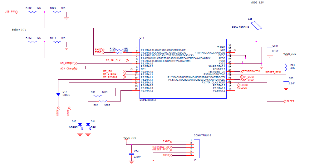
Below is the schematic for the msp + trf circuit

We just had a doubt that may be we are missing something related to the oscillator as many functionalities are using it.
Posting the blocks for the related code where we are initializing the frequency for each functionality.
MSP oscillator calibration:
void
McuOscSel(void)
{
// select DCO to 8MHz

if (CALBC1_8MHZ != 0xFF)
{
// Follow recommended flow. First, clear all DCOx and MODx bits.
// Then apply new RSELx values. Finally, apply new DCOx and MODx bit
// values.
DCOCTL = 0x00;
BCSCTL1 = CALBC1_8MHZ;
DCOCTL = CALDCO_8MHZ;
}

// Disable XT1 pins
P2SEL &= ~(BIT6 + BIT7);

// Disable XT1 high frequency mode, ACLK = 12kHz/4 = 3kHz
BCSCTL1 &= ~XTS;
BCSCTL1 |= DIVA_2;

// Set XT1 to VLO
BCSCTL3 |= LFXT1S_2;

return;
}
SPI configuration:
void
SpiUsciSet(void) //Uses USCI_B0
{
UCB0CTL1 |= UCSWRST; // Enable SW reset
UCB0CTL0 |= UCCKPH + UCMSB + UCMST + UCSYNC; // 3-pin, 8-bit SPI master
UCB0CTL0 &= ~UCCKPH;
UCB0CTL1 |= UCSSEL_2; // SMCLK

UCB0BR0 = 0x04;
UCB0BR1 = 0;
P1SEL |= BIT5 + BIT6 + BIT7; // P1.5,1.6,1.7 UCBOCLK,UCB0SIMO,UCB0SOMI, option select
P1SEL2 |= BIT5 + BIT6 + BIT7; // P1.5,1.6,1.7 UCBOCLK,UCB0SIMO,UCB0SOMI, option select

SLAVE_SELECT_PORT_SET; // P2.1 - Slave Select
SLAVE_SELECT_HIGH; // Slave Select - inactive ( high)

UCB0CTL1 &= ~UCSWRST; // **Initialize USCI state machine**
}
UART initialization:
void
UartSetup(void) // uses USCI_A0
{
// modified for using the ez430-RF256x on the -G2553 LaunchPad
P1SEL |= (BIT2 + BIT1); // P1.2=TXD
// this is for TX only... (short TX & RX on the board P1.1 to P1.2)
P1SEL2 |= (BIT2 + BIT1); // P1.2=TXD

UCA0CTL1 |= UCSWRST; // disable UART

UCA0CTL0 = 0x00;

UCA0CTL1 |= UCSSEL_2; // SMCLK

UCA0BR0 = 0x45; // Baud Rate = 115200
UCA0BR1 = 0x00;

UCA0MCTL = 0; // Modulation UCBRSx = 2

UCA0CTL1 &= ~UCSWRST; // Initialize USCI state machine
UC0IE |= UCA0RXIE;
}
TimerA initialization:
void

McuCounterSet(void)
{
TACTL |= TASSEL_1 + TACLR; // ACLK = 1.5 kHz, timer stopped

TACCTL0 |= CCIE; // compare interrupt enable
}
Thank you
Regards,
Maddineni


