This thread has been locked.

If you have a related question, please click the "Ask a related question" button in the top right corner. The newly created question will be automatically linked to this question.

MSP430G2755: It will be in abnormal operation after changing Batteries or power on-off several times.

Part Number: MSP430G2755
Other Parts Discussed in Thread: MSP-FET

Dears:

The Tags solution is using MSP430G2755.

The system will be in abnormal operation after changing Batteries or power on-off several times.

And the system can not be normal  after Reset.

Could you kindly help give some advice about it.

Thanks a lot!

Luck Wu

  • Hi Lian,

    You mention that the system doesn't return to normal operation even after a reset, and that this is all occurring after some power-cycling or changing of batteries. I would in this case be suspicious of either Flash corruption due to device being operated out of spec during the battery changing or power cycling, or ESD or out-of-spec operation causing damage to the device. We will need more information to try to determine the root cause.

    1) Could you try to read the device out using JTAG or SBW to determine if the Flash area has been corrupted? You could do this for example with the MSP-FET and the Elprotronic Fet-Pro430 Lite software to read out the code image and compare to the TI-txt file code image that you can generate from CCS or IAR. Please let us know if you find any unexpected differences in the image you originally programmed in vs the image in a failing device.

    2) You could also see if re-programming the device causes it to operate normally again?

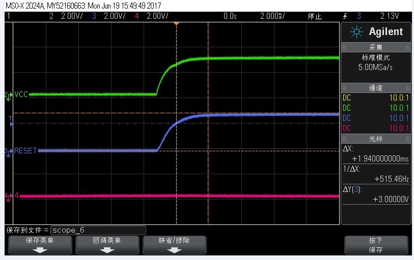
    3) Please monitor Vcc into the MSP430 during the battery change or power-cycling operation, and share the image? Are there spikes on the Vcc? Does Vcc ramp slowly or quickly when powering on?

    4) When you power cycle or change batteries, could any pin on the MSP430 be still at a higher voltage level or sourced by another voltage, while MSP main Vcc is unpowered?

    5) What MCLK frequency do you use in your application?

    6) Check your design for ESD vulnerability per the recommendations in the app note MSP430 System-level ESD Considerations www.ti.com/.../slaa530

    All of these questions are trying to see if there could be any situation where you have the device outside of the ratings in the "recommended operating conditions" section of the datasheet (e.g. system frequency vs supply voltage) or the "absolute maximum rating" section of the datasheet (e.g. voltage applied to any pin spec - like a voltage on a pin while Vcc is much lower, violating the Vcc + 0.3V spec).

    Regards,
    Katie
  • Hi Katie:

    Sorry for my delay reply, pls. kindly refer answers and help to check the issues.

    1) Could you try to read the device out using JTAG or SBW to determine if the Flash area has been corrupted? You could do this for example with the MSP-FET and the Elprotronic Fet-Pro430 Lite software to read out the code image and compare to the TI-txt file code image that you can generate from CCS or IAR. Please let us know if you find any unexpected differences in the image you originally programmed in vs the image in a failing device.

    A: There are not any differences between them.

    2) You could also see if re-programming the device causes it to operate normally again?

    A:It operates normally if re-programming the device.

    3) Please monitor Vcc into the MSP430 during the battery change or power-cycling operation, and share the image? Are there spikes on the Vcc? Does Vcc ramp slowly or quickly when powering on?

     4) When you power cycle or change batteries, could any pin on the MSP430 be still at a higher voltage level or sourced by another voltage, while MSP main Vcc is unpowered?

    A: This application has no other power.

    5) What MCLK frequency do you use in your application?

    A: The MCLK frenquency is 10MHz.

    Many thanks for your support!

    Best regards

    Luck Wu

  • Hi Luck,

    You mentioned that reprogramming the device seemed to fix the issue, even though reading out the flash on the failing unit showed no differences. You also mentioned that a reset doesn't restore functionality. When you were resetting the part, were you doing this via the RST line?

    What if you simply power-cycle the part one more time? Does this also restore functionality?

    In the failing state, can you see if the current consumption is much higher than expected during normal execution? This, along with requiring a power-cycle to resolve vs just a reset, could indicate a latch-up condition which can be caused for example by ESD.

    Regards,
    Katie
  • Hi Luck,

    Any update? Were you able to resolve the issue? What can we do to help further?

    Regards,
    Katie
  • I'm going to close this thread due to inactivity, but please post back if you have any update or further questions.
    -Katie

**Attention** This is a public forum