This thread has been locked.

If you have a related question, please click the "Ask a related question" button in the top right corner. The newly created question will be automatically linked to this question.

MSP430F2013: Analog input (SD16)

Part Number: MSP430F2013

I'm using MSP430F2013 to get analog input voltage. It use SD16 and save count value in SD16MEM0 every 0.256ms . It stop working after few months running. When I plug in MSP430 programmer to check SD16 value and it show 0 even we have voltage input. 40% of our production have this analog issue.

How can I fix that problem OR  is this manufacturing issue?   

Thanks

  • Hi Quan,

    Thanks for posting. To try to determine root cause of what is happening, can you please help provide information for some initial diagnostic questions:

    1. Can you determine if the SD16 is still running (e.g. using the debugger, put something in the SD16MEM0. Does it get overwritten with 0 by a new conversion when you run, or is the value simply not changing at all anymore)?
    2. Do the other functions of the device still appear to be working?
    3. What triggers the SD16 in normal operation - a timer? If so, try to determine if the timer (or other source) is still running? If it's the timer you are checking, should see that the for example TA0R register for the timer count should keep incrementing.
    4. If you read out the full memory of the failing unit, compare it to the code image that should be present in the device - has it changed?
    5. If you reset a failing unit, does it start working again?
    6. If you reprogram a failing unit, does it start working again?
    7. If you swap the parts between a good board and a failing board, does the issue follow the board or the device?

    Regards,
    Katie
  • 1. SD16 does not work anymore, SD16MEM0 show 0 even it have voltage input. look like it can not read input anymore

    2. Other function still work

    3. I don't use timer for SD16. I use frequency to trigger flag

    -----------------------------------------------------------------------------------

    int SD16_init(void){ 
    /* Setup SD16_A on Port A0 for 1MHz*/
    SD16CTL = (SD16XDIV16 + SD16REFON + SD16VMIDON+ SD16DIV4);
    // SD16XDIVx = 010 Source Clock / 16
    // SD16LP = 0 Low Power Disabled
    // SD16DIVx = 00 SD16_A Clock Divide / 1
    // SD16SSELx = 00 Source Clock is MCLK
    // SD16VMIDON = 0 VMID buffer Off
    // SD16REFON = 1.2V Reference Generation On
    // SD16OVIE = 0 Overflow Interrupt Disabled

    SD16CCTL0 = (SD16SNGL + SD16OSR_64);
    // SD16UNI = 0 bipolar mode -Vref/2 -> +Vref/2
    // SD16XOSR = 0
    // SD16SNGL = 1 Single Conversion Mode
    // SD16OSRx = 00 256 Over Sample Rate
    // SD16LSBTOG = 0 SD16LSBACC does not toggle with SD16MEM0 Read
    // SD16LSBACC = SD16MEMx 16-bit conversion data 0: MSB 1: LSB
    // SD16OVIFG = Overflow interrupt Condition
    // SD16DF = 0 Offset Binary
    // SD16IE = 1 SD16_A interrupt Enabled
    // SD16IFG = SD16_A Interrupt flag condition
    // SD16SC = Start Conversion bit

    SD16AE = (SD16_A0p | SD16_A0n);
    // SD16 Input Enable Register Enable SD16_A0 pins

    SD16INCTL0 = (SD16INCH_0);
    // SD16INTDLYx = 00 Fourth Sample causes interrupt
    // SD16GAINx = 000 x1 Pre Amp Gain
    // SD16INCHx = 000 Channel A0

    return 1;
    }

    ---------------------------------------------------------------------------------------------------

    4.No change at all

    5. I reset but nothing change

    6. Still no change

    7. Not work also, If i change new MSP430, it work

    Bonus: If I run SD16 all the time at 1MHz, how long it last. I mean duration . And if I decrease frequency lower to 250kHZ, can it last longer?

    Thanks

  • Hi Quan,

    Thanks for the additional information!

    For #1, I understand that the SD16MEM0 is showing 0 even if there is a voltage input applied. I would like to determine if the issue is that the SD16 stops converting, or if the input pins are somehow damaged or not passing the voltage along to the SD16 (two different failure modes that both could show always 0 in the SD16MEM0. To test this, using the debugger can you write a value into the SD16MEM0, then allow the device to run, and see if the SD16 overwrites the value you put in with a result of 0 - that would indicate that the SD16 still runs and converts, but something is wrong with the input. However, if you write into SD16MEMo, allow the device to run, but it doesn't overwrite that value (the value you wrote in stays), then that could indicate that the SD16 has stopped converting for some reason.

    The fact that reprogramming the device, resetting it, reprogramming it all do nothing, while all other functions still work, and swapping to a new MSP430 works, leads me to believe there must be some hardware issue like damage to the device over time. Could you share what voltage range the MSP430 could be exposed to on its pins? We need to check this against the datasheet specifications for recommended operating conditions and absolute maximum ratings:
    A. Is there ever a voltage beyond Vcc + 0.3V on any pin on the MSP430? This includes while Vcc is still ramping up, e.g. while Vcc is at a lower voltage are there pins on the MSP430 connected to other devices on the board that could be at a higher level than the MSP430 Vcc at that time?
    B. Can you share a diagram of the SD16 pin connections including voltage range that could be seen on the pins?
    C. Could the device be exposed to ESD?

    Regards,
    Katie
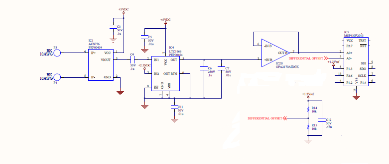
  • This application to measure AC current. A0- = 0.6V(ref) and A0+ get voltage 0 to 1.2V. This system run 24/7 and A0+ ~ 0.8V in almost time. 

    I measure all pin but no pin over Vcc+0.3 and It cannot be exposed to ESD because circuit board is always inside plastic box which protected by chamber panel.

  • Hello Quan,

    Katie's currently out of the office, so I'll do my best to support you. Thanks for providing a portion of your schematic. Initially, I was surprised that the differential voltage inputs weren't connected directly to the +/- pins of the SD16 module of the MSP430F2013, but it looks like you've added some external devices to perform isolation (ACS) and other functions. I'll assume these are working properly.

    I agree with Katie that it's very important that the MSP430F2013 is powered-up before all these other devices are applying input voltages. Assuming you're powering the MSP430F2013 with 3.3VDC (unfortunately, this wasn't shown in your schematic), this would most likely be sourced from the 5VDC rail. Thus, all of these devices (and perhaps others not shown) would power-up first and could be applying voltages above our maximum values to the pins of the MSP430 before VCC equals 3.3VDC. Can you please check this with a scope during start-up? This would explain why the MSP430 would work for a while and then stop working and also why replacing the device is the only way to fix the issue (at least temporarily).

    Also, I noticed that you're configuring the SD16 module to use the internal 1.2V reference, but you also seem to be using an external 1.2V voltage reference as well. I'd strongly recommend that you use one or the other. If you want to output the internal 1.2V reference voltage, you'll need to enable the output buffer and ensure there's a 470nF capacitor is connected between Vref and AVss . If you want to use an external reference input, you'll need to disable the internal 1.2V reference voltage and configure P1.3/VREF correctly.

    Please carefully perform these measurements and resolve the reference voltage source discrepancy before we continue.

    Regards,

    James

    MSP Customer Applications

  • Hi James,

    I think that I use internal 1.2V reference. It was generated from pin P1.3 and Pin A0- get 0.6V which sourced from 1.2V and 2 resistors. And I connect 470nF between P1.3 and Vss also (lower part in schematic). 

    I set up enable output buffer too (SD16VMIDON=1) and MSP430F2013 is on all the time so I'm really sure that the MSP430F2013 is powered-up before all these other devices are applying input voltages.

    My code in previous post is right but I put wrong description (SD16VMIDON = 1 VMID buffer On)

    -----------------------------------------------------------------------------------

    int SD16_init(void){ 

    SD16CTL = (SD16XDIV16 + SD16REFON + SD16VMIDON+ SD16DIV4);
    // SD16XDIVx = 010 Source Clock / 16
    // SD16LP = 0 Low Power Disabled
    // SD16DIVx = 00 SD16_A Clock Divide / 4
    // SD16SSELx = 00 Source Clock is MCLK
    // SD16VMIDON = 1 VMID buffer On
    // SD16REFON = 1.2V Reference Generation On
    // SD16OVIE = 0 Overflow Interrupt Disabled

    SD16CCTL0 = (SD16SNGL + SD16OSR_64);
    // SD16UNI = 0 bipolar mode -Vref/2 -> +Vref/2
    // SD16XOSR = 0
    // SD16SNGL = 1 Single Conversion Mode
    // SD16OSRx = 10 64 Over Sample Rate
    // SD16LSBTOG = 0 SD16LSBACC does not toggle with SD16MEM0 Read
    // SD16LSBACC = SD16MEMx 16-bit conversion data 0: MSB 1: LSB
    // SD16OVIFG = Overflow interrupt Condition
    // SD16DF = 0 Offset Binary
    // SD16IE = 1 SD16_A interrupt Enabled
    // SD16IFG = SD16_A Interrupt flag condition
    // SD16SC = Start Conversion bit

    SD16AE = (SD16_A0p | SD16_A0n);
    // SD16 Input Enable Register Enable SD16_A0 pins

    SD16INCTL0 = (SD16INCH_0);
    // SD16INTDLYx = 00 Fourth Sample causes interrupt
    // SD16GAINx = 000 x1 Pre Amp Gain
    // SD16INCHx = 000 Channel A0

    return 1;
    }

    ---------------------------------------------------------------------------------------------------


  • Hello,

    Thank you for confirming that you're using the internal reference and that the MSP430 is powered-up before the other devices. Also, I missed the 0.47uF capacitor across the resistor ladder in your schematic, so thanks for pointing that out. It seems like your code is working, so I'm concerned there's a hardware issue damaging the device.

    Do you know if this issue occurs at a high temperature?

    Can you confirm that voltage spikes are not damaging the MSP430? I don't see any TVS diodes or varistors on the front-end, although it appears that you're using an isolator. However, what would happen if a spike occurs on the input of the isolator? Does its output respond accordingly?

    After the issue happens, can you share the state of the SD registers? It'd be helpful to see if any interrupt flags are set that could indicate the reason of the issue.

    How repeatable is the issue? Are there specific steps and conditions to make the device fail? If so, please document them and share them.

    Regards,

    James

    MSP Customer Applications
  • Hello,

    Since you mentioned earlier that your differential voltage input range is from -0.6V and 0.6V, I took a look at Section 26.2.2 in the MSP430x2xx User's Guide where it mentions that for a gain of 1 and a 1.2V voltage reference, the maximum full-scale input range is +/-0.6V. Looking at page 43 in the MSP430F2013's datasheet for the specific full-scale input specifications, you can see that for a gain of 1, the recommended full-scale range (FSR) is +/-0.5V (500mV), not +/-0.6V. Also, you can see that Footnote 1 specifies that the "analog input range should not exceed 80% of VFSR+ or VFSR-".

    Also, since you're using Bipolar Offset Binary format, this means that an Analog Input equal to -FSR would cause SD16MEM0 to equal all zeros. This would mean that the input voltage would be equal to zero, since 0V (A0+) - 0.6V (A0-) = -0.6V. You mentioned that "you have voltage input". Did you measure the voltage at the pins of the MSP430 to confirm that the other external devices are actually applying a voltage when the high voltage was applied to the front-end inputs?

    Regards,

    James

    MSP Customer Applications

  • Hello Quan,

    Has you been able to resolve this issue?

    Regards,

    James

    MSP Customer Applications

**Attention** This is a public forum