Because of the Thanksgiving holiday in the U.S., TI E2E™ design support forum responses may be delayed from November 25 through December 2. Thank you for your patience.

This thread has been locked.

If you have a related question, please click the "Ask a related question" button in the top right corner. The newly created question will be automatically linked to this question.

MSP430G2553: Issue with SPI, problem may be in the code.

Part Number: MSP430G2553
Other Parts Discussed in Thread: ENERGIA

I'm trying to program this MSP430G2553 with Energia on a Mac. According to the pin diagram: the SCK should be pin 7, CS pin 8, MOSI pin 15, MISO pin 14. 

I have the uploaded in the board the following code found on the examples code of energia

Problem is that, after uploading a general code for SPI settings (in this case one for barometric pressure measurement), when I check it with a logic analyser it shows the clock and the CS in different positions and the waves don't make sense to me. I have tested the scope with something else and it works so I think that the problem is related either to Energia or to the digram. 

In my project I need to connect an accelerometer (LIS2DH from STmicroelectronics) to the MIC via SPI. So can you help me out somehow?

Either by telling me how to write the code or telling me if I ave done something wrong or if some of the things I said don't make sense to you. 

Thank you very much in advance

  • Hi Edoardo,
    Can you please post a scope shot and your code, and perhaps a schematic?

    I'll look over it and help you find the root of your problem.
  • Sorry I changed a few things. I wrote the code for the accelerometer (using Energia) but still it is not working. Basically it shows the x y and z values as either 0's or -1's and no other changes. From the comments at the beginning of the code and the schematics in the two links below you can see the connections I made.

    www.google.co.uk/url

    www.st.com/.../en.steval-mki135v1_schematic.pdf


    #include <SPI.h>

    /*
    #define DATAOUT 15 //MOSI MSP430G2553 pin 15; LIS2DH SDI pin21
    #define DATAIN 14 //MISO MSP430G2553 pin12; LIS2DH SDO pin22
    #define SPICLOCK 13 //SCK MSP430G2553 pin 7; LIS2DH SCL pin20
    #define cs 8 //CS pin 8; cs LIS2DH pin19, active low, 0: SPI enabled
    */

    //Register Addresses:
    const int OUT_X_L = 0x28; //X-axis acceleration data
    const int OUT_X_H = 0x29;
    const int OUT_Y_L = 0x2A; //Y-axis acceleration data
    const int OUT_Y_H = 0x2B;
    const int OUT_Z_L = 0x2C; //Z-axis acceleration data
    const int OUT_Z_H = 0x2D;

    int CS = 8;

    int readRegister(byte x) {
    int r=0;
    byte b = x| (0b10000000);

    digitalWrite (CS, LOW);
    SPI.transfer(b);
    r = SPI.transfer (0x00);
    digitalWrite (CS, HIGH);
    return r;
    }


    int readval (int x) {
    int val;
    byte h, l;

    if (x==1) {
    l = readRegister(OUT_X_L);
    h = readRegister(OUT_X_H);
    }
    else if (x == 2) {
    l = readRegister(OUT_Y_L);
    h = readRegister(OUT_Y_H);
    }
    else if (x == 3) {
    l = readRegister(OUT_Z_L);
    h = readRegister(OUT_Z_H);
    }
    val = (h<<8) | l;
    return val;
    }


    void setup()
    {
    delay(500);
    pinMode(CS,OUTPUT);

    SPI.begin();
    //our device requires data to be sent MSB
    //(most significant byte) first, pg. 23
    SPI.setBitOrder(MSBFIRST);
    //clock is idle high and data is shifted in and out
    //on the rising edge of the data clock signal, pg. 23
    SPI.setDataMode(SPI_MODE3);
    SPI.setClockDivider(SPI_CLOCK_DIV2);
    //Create a serial connection to display the data on the terminal.
    Serial.begin(9600);
    delay(500);
    }

    void loop()
    {
    Serial.print(" x = ");
    Serial.print(readval(1));
    Serial.print(" y = ");
    Serial.print(readval(2));
    Serial.print(" z = ");
    Serial.println(readval(3));
    delay (500);

    }
  • Using a scope, are you seeing a clock on the SCK line? I see that you have selected pin 13 in your code, but if I'm not mistaken, the energia library uses pin 13 for the SCK.

    Are you seeing any data on the MISO and MOSI lines? If so, what data and on which lines?
  • I don't see a clk and no data in MISO and MOSI.
    I connected the SCK to pin 7 (P 1.5) according to this.
    energia.nu/.../

    Any idea of what the problem might be?

    Kind regards
    Edoardo Occhipinti
  • Edoardo,

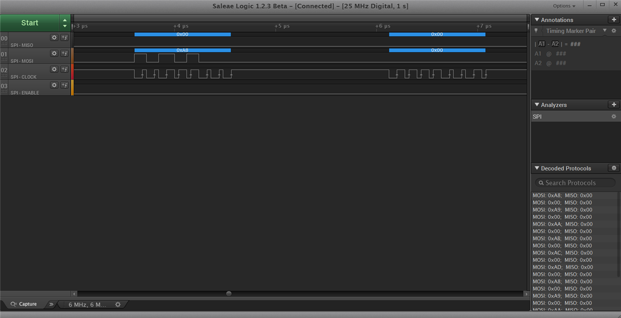
    I ran your code with a logic analyzer and everything looks as it should, I see the 6 addresses and the response frame (no data since I don't have your sensor). See below. If you are zoomed very far out, these exchanges may be easy to miss...

    Are you sure your connections are correct?

  • Closing due to inactivity.

**Attention** This is a public forum