Other Parts Discussed in Thread: LM5111, , MSP430F5529
Tool/software: Code Composer Studio
Hello,
I am generating two variable duty cycle PWMs based on a analog voltage. One PWM output is the inversion of the other. This PWM outputs is connected to the LM5111 gate driver to drive FETS to control LED brightness. When I run the code there is a period where both PWM outputs are low which causes the LED driver to restart. Therefore the LEDs are blinking rather than being ON continuously.
I am using the msp430FR2311 Lanchpad and code composer to generate code for the PWM outputs. UP/DOWN timer mode is being used on the timer. I am reading the analog voltage on P1.4 and I am generating the PWM signals on P1.6 and P1.7.
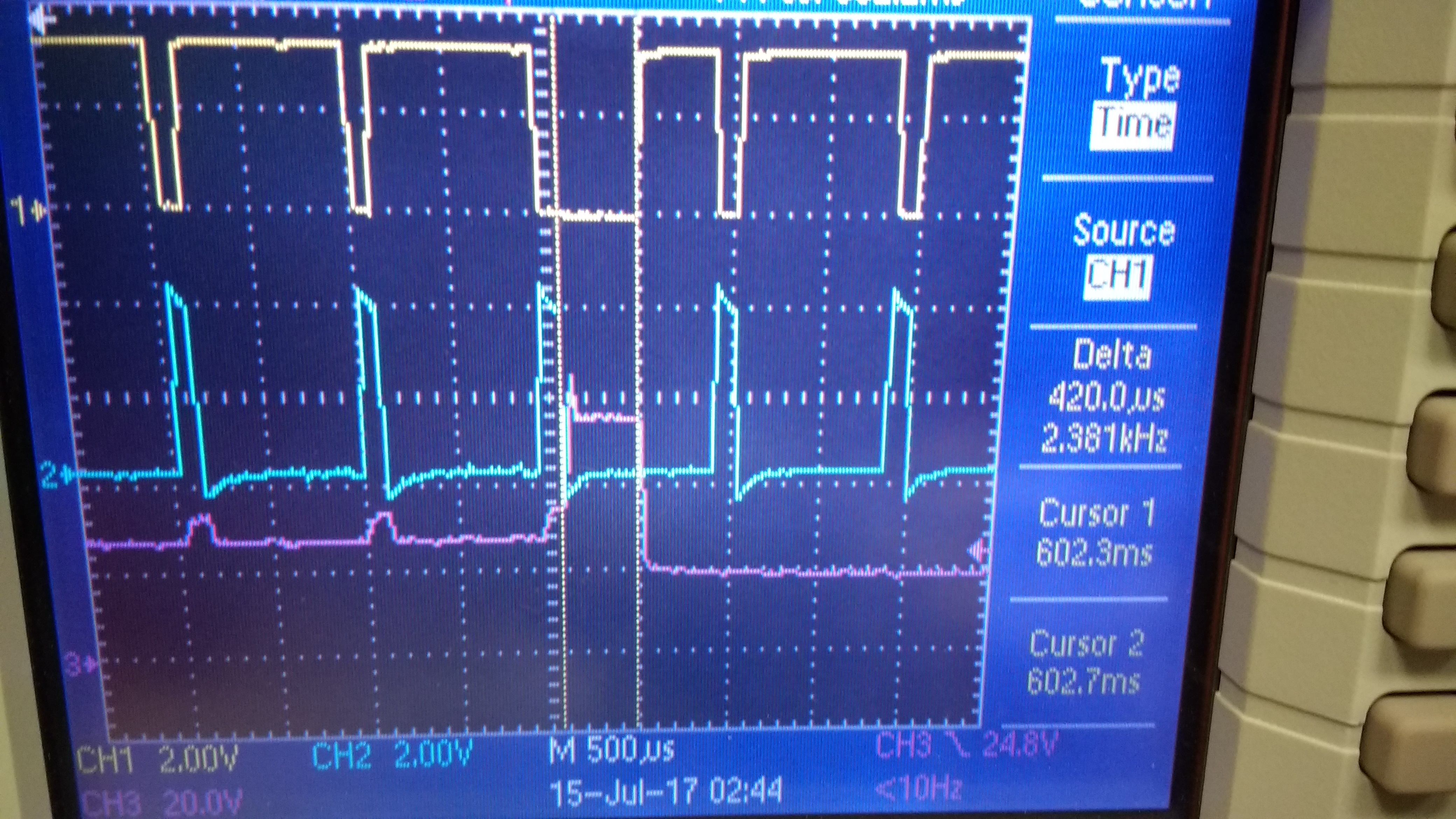
I have attached two images. In the first image the top two waveforms are the PWM outputs and the bottom waveform is the LED driver voltage. The top(yellow) waveform has a glitch. In the second image the two waveforms are the PWM outputs. Notice the bottom waveform has a glitch. Is it a problem to use the same port for timer outputs and a ADC reading?