This thread has been locked.

If you have a related question, please click the "Ask a related question" button in the top right corner. The newly created question will be automatically linked to this question.

MSP430F6779: Behavior when switching with AUX

Expert 2780 points

Part Number: MSP430F6779

Hello,

I have a question about the Behavior of AUX.

Connect the power supply (3.3 v) to DVCC and connect the battery (about 3.0 V) to AUXVCC1.
Set AUX to hardware control.

When the power supply to DVCC is turned off, it switches to AUXVCC1, but the voltage of AUXVCC1
drops for a moment.

Q1
Is it normal for the voltage of AUXVCC1 to drop when switching?

Q2
AUXVCC1 falls from 3.0v to 2.7v, then it returns to 3.0v.
Is this a problem of making hardware?

Q3
Is there a way to suppress voltage drop?
(capacitor and layout?)

Regards,
DA

  • Hi Da,

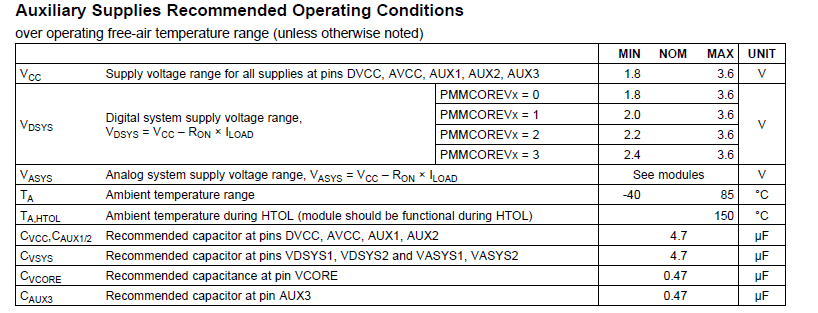
    Can you ensure you're following the recommend operating conditions specified in the Auxillary Supplies Recommended Operating Conditions section of the datasheet. More specifically, please ensure you have the appropriate capacitance on Vcc, Aux1, Aux2, Vsys, Vcore, etc:

    Best regards, 
    Caleb Overbay

  • In customer's environment, voltage drop can not be prevented with 10 micro F capacitor.

    It is a result confirmed in my environment.
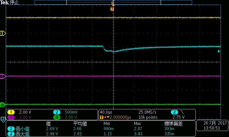
    AUXVCC 0: Power supply( 3.0v -> OFF )
    AUXVCC 1: Battery (CR 2032) : Capacitor 4.7uF + 0.1uF

    Yellow : AUXVCC0
    Blue : AUXVCC1  ( min 2.69v / max 2.99 )

    This is the waveform when the power supply of  AUXVCC0 is turned off in the LPM3 state.

    Question

    About the drop of voltage at this switching, is there a numerical value (or guideline) of how much current flows?
    ( mA, mW ... )

    Regards,

    DA

  • Hi Da,

    This might be due to the fact that the AUXVCC1 supply is a battery with low resistance. Can you try supplying AUXVCC1 from a 3V bench supply and observe if the same behavior occurs? If the bench supply does not exhibit this same behavior, then we know it is because of the low resistance nature of the battery. In this case I would recommend adding a resistor in series with the battery to limit the current to the MSP430 when switching occurs.

    Best regards,
    Caleb Overbay
  • Hi Caleb,
    Thanks your replay.

    A series resistance was added and confirmed by EVM, but there was no change.

    Customer information: Voltage drops even if DVcc and AUXVCC1 are switched by software.

    As an experiment, DVCC and AUXVCC1 were switched by software, and the voltage of DVCC was changed.
    As a result, we found that this depression is changed by the difference between DVCC and AUXVCC1.

    From DVcc to AUXVcc1
    DVCC < AUXVCC1: drop (previous waveform is this condition)
    DVCC > AUXVCC1: rise
    DVCC = AUXVCC1: none

    Is this rise and drop when switching different power supplies?

    Regards,
    Da

  • Hi Da, 

    I'm having a little trouble understanding your latest post. To summarize:

    1. When DVCC is less than AUXVCC1 (DVCC < AUXVCC1) you see a voltage drop on AUXVCC1 during switch
    2. When DVCC is greater than AUXVCC1 (DVCC > AUXVCC1) you see a voltage rise on AUXVCC1 during switch
    3. When the two voltages are equal, there is no voltage interruption

    Were you always using the battery as the AUXVCC1 supply during these tests? Did you try using a bench supply?

    Best regards, 
    Caleb Overbay

  • Hi Caleb,

    I am experimenting with connecting the battery (CR2032) to AUXVcc1.


    It is an additional question.
    Can I think that the voltage of AUXVCC1 is not less than DVCC?


    Regards,
    Da
  • Hi Da,

    Before answering your question, can you observe the results when AUXVCC1 is supplied from a bench supply and not from the battery?

    I highly suspect this issue is inherent to the physical properties of the battery.

    Best regards,
    Caleb Overbay
  • Hi Caleb,

    I performed experiments using "Regulated DC power supply", but it decreased, but there was a drop in voltage.

    (In this experiment, DVCC and AUXVCC are switched by software without changing the external state.)

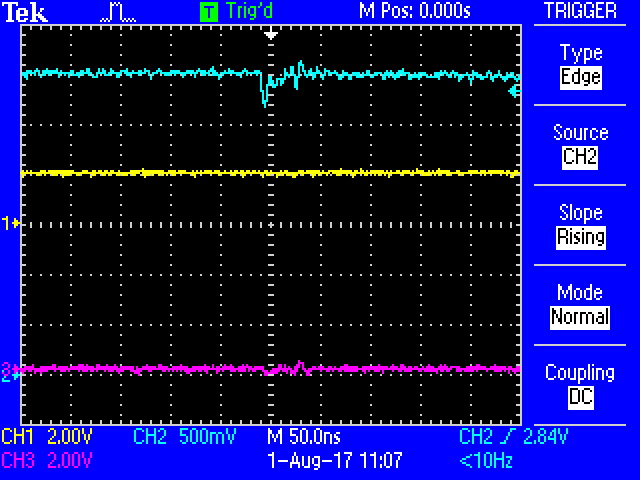
    Yellow : DVCC = 2.0v / Blue : AUXVCC = 3.0v / Purple : GPIO(event Trigger)

    An enlarged part of the above voltage drop. There is something like noise before the voltage drop.

    Regards,
    Da

  • Hi Da,

    I apologize for the late reply. The notification for this post got lost in my inbox. I just tested this out on my own setup and was able to observe a voltage dip when using the CR2032 battery on AUXVCC1 when DVCC was removed. However, when I tested this out using a 3.0V bench supply on AUXVCC1 instead of the CR2032, I did not see any kind of voltage drop.

    I think what you're observing here is caused by the inability of your power supply to quickly compensate for the sudden current draw placed on AUXVCC1 when DVCC is turned off. I don't think this is behavior is caused by the MSP430. I need to speak with some colleagues to provide some suggestions for workarounds but I'll get back to you soon.

    Best regards,
    Caleb Overbay
  • Hi,

    OK. Please give a workaround.

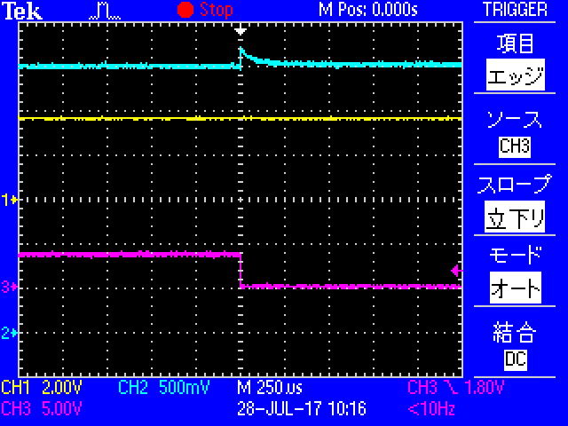
    In the test, it is the waveform when DVCC is switched from DVCC to AUXVCC1 when DVCC is 3.6 v and AUXVCC 1 is 3.0 v.
    In this case it was not a drop but the voltage was up.

    2:blue : AUXVCC1

    Regards,
    Da

  • Hi Da,

    First I'd like to thank you for all the information you've provided. I see that you are using the MSP430F6679 for this application and I'd like to recommend that you switch to the MSP430F6679A. There were several updates made to the aux power module in this revision and they are pin for pin compatible. You can find more information on the differences between the A and non-A versions in Differences Between MSP430F67xx and MSP430F67xxA Devices.

    Also, is it possible to use AUXVCC2 instead of AUXVCC1 for this application? When using a battery such as the CR2032 as an auxiliary source, it's more suitable to use AUXVCC2 because of the internal charging circuitry. This circuitry is fed from the DVCC line and can be used to charger external caps. In this scenario you would also want to include a diode between the capacitors and your battery to avoid charging the battery when DVCC is applied. 

    Finally, I recommend taking a look at Battery Management and Auxiliary Battery Supply Options for E-meters. This document can provide more detail to my comments in this post. It explains the differences between the AUXVCCx inputs and how to choose the best auxiliary power setup for your application. Overall, I think the issue you're experiencing can be alleviated by using AUXVCC2 instead of AUXVCC1.

    Best regards,
    Caleb Overbay 

  • Thank you for information.

    Q1:
    I referred to the document. Will voltage drop be relaxed if I change to version A with this change contents?

    Q2:
    With the AUX module, is it specification whether power is dropped when switching power supply?

    Q3:
    Do you know how much power will be dropped?

    Q4:
    Will AUXVCC 2 have less power drop?

    I switched from AUXVCC 1 to AUXVCC 2 and measured it.
    However, the power drop was almost the same.
    (The algorithm has not been modified + the diode is not connected)

    Best Regards,
    DA

  • Hi Da,

    da said:
    Q1:
    I referred to the document. Will voltage drop be relaxed if I change to version A with this change contents?

    The changes are most likely not affecting the behavior you are currently seeing. However, this does not mean that sometime in the future that the issues fixed in the A revision will affect your operation on the non-A revision. 

    da said:
    Q2:
    With the AUX module, is it specification whether power is dropped when switching power supply?

    No, this is not specified because it is not dependent on the MSP430. The drop in the power supply you're observing is entirely dependent on the ability of the power supply to compensate for a sudden change in current draw (when DVCC switches to AUXVCCx). For a battery, there is no compensation loop so the dip is more drastic than if you use a bench supply. 

    da said:
    Q3:
    Do you know how much power will be dropped?

    This is something dependent on your application and the battery being used. 

    da said:
    Q4:
    Will AUXVCC 2 have less power drop?

    I would suspect that the charging circuit internal to AUXVCC2 would be able to charge the external cap(s) to the 3.6V and help alleviate the voltage drop. There is a possibility that since you don't have a diode, the current is flowing into the battery and not fully charging the cap. I'll need to speak further with my colleagues to understand this behavior and I'll get back to you soon.

    Best regards, 
    Caleb Overbay

  • Hi Da,

    I wanted to touch base and let you know that I am still working on this. Currently I'm in discussions with the teams responsible for the auxiliary module to understand why the behavior is occurring and what can be done to alleviate the issue. These teams are all across the world so coordination takes a some time. I'll keep you updated as the discussions progress.

    Best regards,
    Caleb Overbay
  • Hi Da,

    I'm going back through your posts and there seems to be some conflicting information that I need to clarify. In your setup, what happens to AUXVCCx when the following conditions are present during the switch:

    1. DVCC > AUXVCCx
    2. DVCC < AUXVCCx
    3. DVCC = AUXVCCx

    Best regards, 
    Caleb Overbay

  • Hi, Caleb

    I checked about AUX.
    Software swtich 1, 2, 3
    + Hardware switch

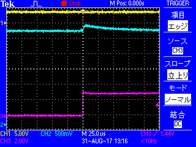
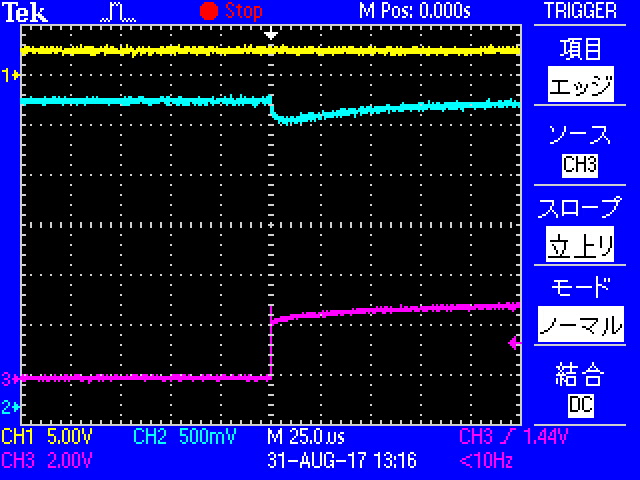
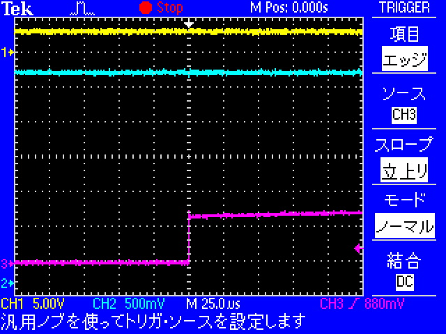
    <When switching using software.>

    Case 1 : yellow:DVCC = 3.6v(power supply), Light blue:AUXVCC1 = 3.0v(battery)

    Case 2 : yellow:DVCC = 2.4v(power supply), Light blue:AUXVCC1 = 3.0v(battery)

    Case 3 : yellow:DVCC = 3.0v(power supply), Light blue:AUXVCC1 = 3.0v(power supply) 

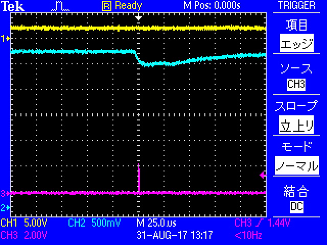
    <When switching using hardware.>

    Case  : yellow:DVCC = 3.6v(power supply) ---> OFF  , Light blue:AUXVCC1 = 3.0v(battery)

    Regards,
    DA

  • Hi Da, 

    Thank you for your patience. It's been a while since my last response and in the meantime I've been collecting data and troubleshooting a possible solution to the voltage dip. Overall, the dip or glitch you observed on AUXVCC when switching doesn't appear to impact VDSYS and therefore there is no impact to the functionality of the whole MSP because it is supplied by the non-disturbed VDSYS. 

    There is a current flowing in our out of DVCC during supply switching depending on the relation between DVCC and AUX supply (DVCC < AUX --> dip, DVCC > AUX --> spike). Measurements confirmed that a peak current up to ~250 mA might flow into DVCC in case of the voltage dip. However the peak current is not specified nor characterized therefore we do not have any data on it.

    But based on the experiments we know that some supplies like a CR2032 battery cannot supply the peak current which leads to a supply dip! If supplied with power supply the dip will not appear. Because this dip has not influence to the functionality I don't recommend spending more effort trying to eliminate the dip. Let me know if you have any comments or questions. 

    Best regards, 
    Caleb Overbay

  • I was waiting for your answer.

    It was found that VDSYS was not affected and there was no problem with internal operation.


    Would you like to ask additional questions?
    I understand that you dip AUXVCC, but will this happen to SVSH at this time?
    Does that mean that SVSH settings must be set by anticipating this dip?

    Best Regards,
    Da

  • Hi Da, 

    I would set the SVSH settings to anticipate this dip. If I remember correctly the dip was right on the edge of the default SVSH threshold. If you need help changing the SVSH settings let me know and we can work from there. 

    Best regards, 
    Caleb Overbay

**Attention** This is a public forum