This thread has been locked.

If you have a related question, please click the "Ask a related question" button in the top right corner. The newly created question will be automatically linked to this question.

MSP432P401R: UART 1MHz get overrun error

Part Number: MSP432P401R

Hello,

need help on following issue.

Have a setting of 2 eva boards one is MSP432P401R another TM4C both from TI.

both are running UART echo example slightly modified. UART freq 1MHz.

TM4C UART sender, MSP432 is receiver.

TM4C is sending a package of 256 byte with DMA activated.

MSP432 is getting is with UART overrun error.

I go down with UART freq and all is okay..

Question, what can be done to get rid of UARToverrun error on receiver side?

Thanks

  • Hello,

    Let us run a few tests and we will get back to you.

    Thanks,

    David
  • Hello Yuliy

    Is there any form of flow control implemented between the two Transmitter and Receiver boards? Note that the TM4C device may be running at high system frequency allowing it to transmit almost back to back frame and thereby overwhelming the receiver device.
  • Hello Amit

    >Is there any form of flow control implemented between the two Transmitter and Receiver boards?

    not sure, what you are asking... per definition DMA means now flow control, I just configure and than enable channel.. DMA informs me when the transmission is ready by interrupt calling..

    >Note that the TM4C device may be running at high system frequency allowing it to transmit almost back to back frame and thereby overwhelming the receiver device.

    Agree,... so what? the 1MHz UART freq is legal and within the limit of what is promised in documentation. UART must be capable to process this stream.

  • Hello Yuliy,

    From the TM4C device perspective 1Mbps UART is within operating specification for sure and it should be operating at 1Mbps baud rate. However at the MSP432P401 device side, which is the receiver, if the UART is receiving the data and is processing it then we have a potential problem. The UART on the MSP432P401 device does not have a FIFO like the TM4C device. Hence we receiving data and processing it, there is a potential for the UART to over run while the CPU is processing the data. To overcome such a scenario what needs to be implemented is a SW FIFO and a SW flow control

    In other words,
    Step-1 : when sending data from the Tx to Rx, send data in chunks of predefined byte sizes, e.g. 32. When these bytes are received the Tx waits for an ACK byte from the Rx.
    Step-2 : The Rx processes the data and once done only then sends the ACK back to the Tx module.

    This will ensure that the CPU does not get bogged down with processing while data gets over-run.

    Alternatively the interrupt must be used on the Rx side to inform the CPU that data is coming through and the application must ensure that the processing of the data does not occur in the interrupt handler. If the processing of the data is done in the interrupt handler, then the CPU cannot accept the next interrupt as it is still in the interrupt handler.
  • >Step-1 : when sending data from the Tx to Rx, send data in chunks of predefined byte sizes, e.g. 32

    I tried this, it doesn't work even with 2 bytes.. not to speaking about 32..

    >The Rx processes the data and once done only then sends the ACK back to the Tx module.

    it doesn't work in RX-processes-the-data step... there is no received data, overrun state hence nothing to confirm. acknoledgment

    >This will ensure that the CPU does not get bogged down with processing while data gets over-run.

    Sorry. doesnt work. I tried DMA with UART... also did not help.

    >Alternatively the interrupt must be used on the Rx side to inform the CPU that data is coming through 

    sorry, I dont get it.. you write "is coming".. you mean in the middle of 32 byte chunk?

    What interrupt number you mean?

    I know the interrupt for has-been-received..

  • >Let us run a few tests and we will get back to you.
    have you run some of tests?

    what are results?
  • Hello Yuliy

    What does the MSP432P401R device does when it received the first byte?
  • Amit Ashara said:
    Hello Yuliy

    What does the device does when it received the first byte?

    What the Chip does in Firmware I do not know

    But  in my Application, nothing special.

    It is just modified echo example.  One thread,  nothing more.

  • Hello Yuliy

    I am not sure what firmware are you referring to here. Are you using the RTOS environment on the SDK or the DriverLib to develop the application code?
  • I use both. Create the tirtos thread.  Iside the tread i prepare DMA with driver lib. But directly  interrupt i cannot use. I use hwi instead.

    Is it not legal?

    You did not answered me.

    Have you run your tests?

  • I still have the problem.
    I can do bare metal example of UART DMA RX, the UART is up to 3,6 Mhz is working but only if i put some small pause between each byte.
    so overall speed is much slower 700khz. I reduce the byte-between-pause. I see overrun error on UART..

    What can you advise me?
    I am within documentation promised UART speed...
  • Hello Yuliy,

    Can you please post the code and the settings for the MSP432P401R device along with the setup you are using to test the same? Having high baud rate does not mean neccessarily that the device may be able to process it. As a hypothetical scenario if the data being received has to be processed through a complicated mathematical run e.g. FFT, then it may result in data being lost. What it allows is the minimal time for transferring the data.
  • I will send sources in 5 or 6 hours.. later, sorry.

    >Having high baud rate does not mean neccessarily that the device may be able to process it.
    you say device may be able process.. you mean UART driver? overrun error comes ONLY from UART driver.
    CPU is nothing to do here.. am I right?
    But according to the documentation UART is capable of speed speed 3-5-7 MHz..
    I just expect what is promised in documentation.

    Will post source later today..
  • So, as I promised that is my code that runs on MSP432.

    As I said, I can run UART with freq 3,6 MHz but only if each byte is separated with small time pause between, So in fact reducing my overall byte stream speed. From 3,6 MHz to 700khz.

    What is my manager ask me just what is promised in MSP432 documentation nothing more. And he is right.

    /* DriverLib Includes */
    #include <ti/devices/msp432p4xx/driverlib/driverlib.h>
    
    /* Standard Includes */
    #include <stdint.h>
    #include <stdbool.h>
    
    static DMA_ControlTable dmaControlTable[8];
    
    static void prepareDMA()
    {
        MAP_DMA_enableModule();
        MAP_DMA_setControlBase(dmaControlTable);
        /* Assign DMA channel 0 to EUSCI_A0_TX0 */
        MAP_DMA_assignChannel(DMA_CH0_EUSCIA0TX);
    
        /* Setup the TX transfer characteristics & buffers */
        MAP_DMA_setChannelControl(DMA_CH0_EUSCIA0TX | UDMA_PRI_SELECT,
        UDMA_SIZE_8 | UDMA_SRC_INC_8 | UDMA_DST_INC_NONE | UDMA_ARB_1);
        MAP_DMA_assignInterrupt(INT_DMA_INT1, DMA_CHANNEL_0);
        MAP_DMA_disableInterrupt(INT_DMA_INT1);
    
        /* Assign DMA channel 1 to EUSCI_A0_RX0 */
        MAP_DMA_assignChannel(DMA_CH1_EUSCIA0RX);
        /* Setup the RX transfer characteristics & buffers */
        MAP_DMA_setChannelControl(DMA_CH1_EUSCIA0RX | UDMA_PRI_SELECT,
                                  UDMA_SIZE_8 | UDMA_SRC_INC_NONE | UDMA_DST_INC_8 | UDMA_ARB_1);
        MAP_DMA_assignInterrupt(INT_DMA_INT2, DMA_CHANNEL_1);
        MAP_DMA_disableInterrupt(INT_DMA_INT2);
    }
    
    static void UART_send_dma(char *buff, int n)
    {
        MAP_DMA_setChannelTransfer(
                DMA_CH0_EUSCIA0TX | UDMA_PRI_SELECT,
                UDMA_MODE_BASIC,
                buff,
                (void *) MAP_SPI_getTransmitBufferAddressForDMA(EUSCI_A0_BASE), n);
    
        MAP_DMA_enableInterrupt(INT_DMA_INT1);
        MAP_Interrupt_enableInterrupt(INT_DMA_INT1);
        MAP_DMA_enableInterrupt(INT_DMA_ERR);
        MAP_Interrupt_enableInterrupt(INT_DMA_ERR);
        MAP_DMA_enableChannel(DMA_CHANNEL_0 );
    }
    
    static void UART_receive_dma(char *buff, int n)
    {
        MAP_DMA_setChannelTransfer(
                DMA_CH1_EUSCIA0RX | UDMA_PRI_SELECT,
                UDMA_MODE_BASIC,
                (void*)MAP_SPI_getReceiveBufferAddressForDMA(EUSCI_A0_BASE),
                buff, n);
        MAP_DMA_enableInterrupt(INT_DMA_INT2);
        MAP_Interrupt_enableInterrupt(INT_DMA_INT2);
        MAP_DMA_enableInterrupt(INT_DMA_ERR);
        MAP_Interrupt_enableInterrupt(INT_DMA_ERR);
        MAP_DMA_enableChannel(DMA_CHANNEL_1);
    }
    
    struct Stat
    {
        uint32_t time;
        uint32_t errCnt;
        uint32_t cnt;
        uint8_t num;
        uint8_t indx;
        uint32_t errIndx;
    }stat = {0,0,0,0,1,0};
    
    struct ErrStat
    {
        char soll;
        char ist;
    }errStat = {0,0};
    
    static uint32_t timeStamp;
    static bool receive;
    
    static void prepareUART()
    {
        const eUSCI_UART_Config uartConfig =
        {
                EUSCI_A_UART_CLOCKSOURCE_SMCLK, // SMCLK Clock Source
                6,                              // BRDIV = 78
                0,                              // UCxBRF = 2
                6,                              // UCxBRS = 0
                EUSCI_A_UART_EVEN_PARITY,       // No Parity
                EUSCI_A_UART_LSB_FIRST,         // LSB First
                EUSCI_A_UART_ONE_STOP_BIT,      // One stop bit
                EUSCI_A_UART_MODE,              // UART mode
                0                               // Oversampling
        };
    
        /* Selecting P1.2 and P1.3 in UART mode */
        MAP_GPIO_setAsPeripheralModuleFunctionInputPin(GPIO_PORT_P1,
                GPIO_PIN1 | GPIO_PIN2 | GPIO_PIN3, GPIO_PRIMARY_MODULE_FUNCTION);
    
        /* Setting DCO to 24MHz */
        CS_setDCOCenteredFrequency(CS_DCO_FREQUENCY_24);
    
        /* Configuring UART Module */
        MAP_UART_initModule(EUSCI_A0_BASE, &uartConfig);
        MAP_UART_selectDeglitchTime(EUSCI_A0_BASE, EUSCI_A_UART_DEGLITCH_TIME_2ns);
        /* Enable UART module */
        MAP_UART_enableModule(EUSCI_A0_BASE);
        MAP_Interrupt_enableMaster();
    }
    
    static void prepareTimer()
    {
        MAP_Timer32_initModule(TIMER32_BASE, TIMER32_PRESCALER_1, TIMER32_32BIT,
                TIMER32_FREE_RUN_MODE);
        MAP_Timer32_startTimer(TIMER32_BASE, true);
        timeStamp = MAP_Timer32_getValue(TIMER32_BASE);
    }
    
    static void errAnalyse2(char* buff)
    {
        bool e1 = !(abs(buff[stat.indx]-stat.num) == 1) && buff[stat.indx];
        bool e2 = buff[0]+stat.indx != 128;
        if (e1 || e2)
        {
            ++stat.errCnt;
            stat.errIndx = e1? 1:2;
            if (e1)
            {
                errStat.ist = buff[stat.indx];
                errStat.soll  = stat.num +1;
            }
        }
    
        stat.indx = (128>buff[0])? 128-buff[0]:stat.indx;
        ++stat.cnt;
        stat.num = buff[stat.indx];
    
        uint32_t newTime = MAP_Timer32_getValue(TIMER32_BASE);
        stat.time = timeStamp - newTime;
        timeStamp = newTime;
    }
    
    void errAnalyse(char* buff)
    {
        uint8_t e1 = !buff[stat.indx] || abs(buff[stat.indx]-stat.num) == 1;
        if (!e1)
        {
            ++stat.errCnt;
            errStat.ist = buff[stat.indx];
            errStat.soll  = stat.num + 1;
            stat.indx = (128>buff[1])? 129-buff[1]:stat.indx;
            stat.indx = (stat.indx == 128)? 0:stat.indx;
            stat.num = buff[stat.indx];
        }
        else
        {
            stat.num = buff[stat.indx];
            ++stat.cnt;
        }
        uint32_t newTime = MAP_Timer32_getValue(TIMER32_BASE);
        stat.time = timeStamp - newTime;
        timeStamp = newTime;
    }
    int main(void)
      {
        char buff[256];
        uint32_t i;
        MAP_WDT_A_holdTimer();
    
        prepareUART();
        prepareDMA();
        prepareTimer();
    
        /* to prepare osci  */
        _delay_cycles(24000000);
    
        while (1)
        {
            receive = 1;
            UART_receive_dma(buff, 128);
            while(receive);
            errAnalyse(buff);
        }
    
        memset(buff,0x00,256);
        for(i=0;i<128;++i)
            buff[i] = i;
    
        while(1)
        {
            receive = 1;
            ++buff[0];
            UART_send_dma(buff, 128);
            while(receive);
            ++stat.cnt;
            _delay_cycles(48);
        }
    }
    
    void DMA_INT2_IRQHandler(void)
    {
        MAP_DMA_clearInterruptFlag(DMA_CHANNEL_1);
        receive = 0;
    }
    
    void DMA_INT1_IRQHandler(void)
    {
        MAP_DMA_clearInterruptFlag(DMA_CHANNEL_0);
        receive = 0;
    }
    
    void DMA_ERR_IRQHandler(void)
    {
        MAP_DMA_clearInterruptFlag(DMA_CHANNEL_1);
        MAP_DMA_clearInterruptFlag(DMA_CHANNEL_2);
        receive = 0;
    }
    
    void EUSCIA0_IRQHandler(void)
    {
        uint32_t status = MAP_UART_getEnabledInterruptStatus(EUSCI_A0_BASE);
        uint32_t errors = MAP_UART_queryStatusFlags(EUSCI_A0_BASE,
                                                    EUSCI_A_UART_FRAMING_ERROR|
                                                    EUSCI_A_UART_OVERRUN_ERROR|
                                                    EUSCI_A_UART_PARITY_ERROR);
    
        MAP_UART_clearInterruptFlag(EUSCI_A0_BASE, status);
    
        if(status & EUSCI_A_UART_RECEIVE_INTERRUPT_FLAG)
        {
            //MAP_UART_transmitData(EUSCI_A0_BASE, MAP_UART_receiveData(EUSCI_A0_BASE));
        }
    
    }
    

  • Hello Yuliy,

    What is the source of the data to the MSP432P401R device and what is the system clock setup for the MSP432P401R device; could you please share the same information?
  • >What is the source of the data to the MSP432P401R device?

    EK_TM4C129EXL, running modified uart dma echo example

    >what is the system clock setup for the MSP432P401R

    sorry I do not understand what sys clock setup I must give you? I sent you full my source code in my first post...

    Do you mean that?

        /* Setting DCO to 24MHz */
        CS_setDCOCenteredFrequency(CS_DCO_FREQUENCY_24);
    At least you can compile/flash my code and investigate all the CPU register etc. whatever you want..

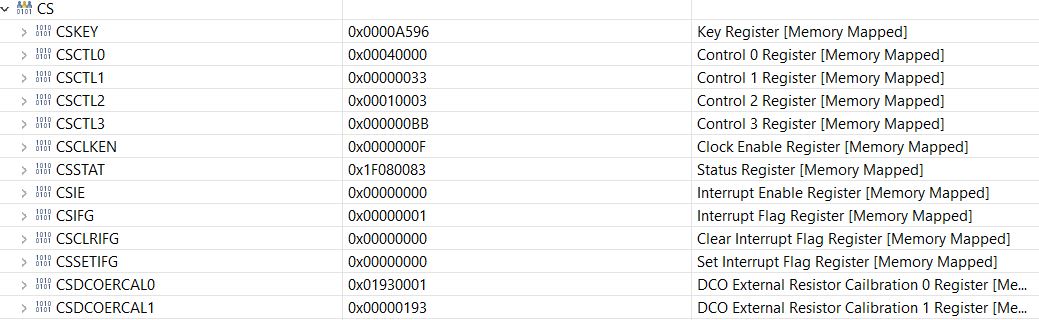
  • Also I do provide a snapshot of CS registers, if it helps.

  • Hello Yuliy,

    Since you are using the UART with 24MHz clock it is required to set the voltage to 1.4V. As per the device datasheet an SMCLK of 24MHz can be provided only when VCORE=1.4V. Otherwise it must be scaled down to 12MHz.
  • I tried both

    MAP_PCM_setCoreVoltageLevel(PCM_VCORE0);  

    MAP_PCM_setCoreVoltageLevel(PCM_VCORE01);

    in both cases max UARTRX freq is 3,6 MHz... well below promised in spec..

    once more initialisation code

        const eUSCI_UART_Config uartConfig3MHz6 =
        {
                EUSCI_A_UART_CLOCKSOURCE_SMCLK, // SMCLK Clock Source
                6,                              // BRDIV
                0,                              // UCxBRF
                6,                              // UCxBRS
                EUSCI_A_UART_EVEN_PARITY,       // No Parity
                EUSCI_A_UART_LSB_FIRST,         // LSB First
                EUSCI_A_UART_ONE_STOP_BIT,      // One stop bit
                EUSCI_A_UART_MODE,              // UART mode
                0                               // Oversampling
        };
    
        /* Selecting P1.2 and P1.3 in UART mode */
        MAP_GPIO_setAsPeripheralModuleFunctionInputPin(GPIO_PORT_P1,
                GPIO_PIN1 | GPIO_PIN2 | GPIO_PIN3, GPIO_PRIMARY_MODULE_FUNCTION);
    
        /* Setting DCO to 24MHz (upping Vcore) */
        MAP_PCM_setCoreVoltageLevel(PCM_VCORE0); //PCM_VCORE1
        CS_setDCOCenteredFrequency(CS_DCO_FREQUENCY_24);
    
        /* Configuring UART Module */
        MAP_UART_initModule(EUSCI_A0_BASE, &uartConfig3MHz6);

    Sorry, cannot get it working for rx more then 3.6 MHz..

  • Rx Overrun is (almost) always a function of software, not hardware. It is (theoretically) possible to overwhelm the DMA by asking it to do too many things, but you're not doing that here. You can't "overrun" the UART at a bit level since it's just a polling engine.

    "modified dma uart echo example" sounds like the transmitter is sending a continuous stream. This means that your software has (6*10) clocks -- not much time -- to restart the Rx DMA to capture the 129th byte before the UART overruns.

    I suggest you try Circular DMA and work with half-buffers, or at least re-order your main() loop so that it restarts the DMA (probably with a different buffer) immediately after the Rx is complete.
  • >"modified dma uart echo example" sounds like the transmitter is sending a continuous stream. 

    not continuous, Sender sends a buffer of 256 bytes, exactly what is set up of receiver UART. then pause of 20 microsec, then again buffer is sent,

    > not much time -- to restart the Rx DMA to capture the 129th byte

    20 microsec is enough time, I suppose. 

    > it restarts the DMA (probably with a different buffer) immediately after the Rx is complete.

    different buffer, that I did not tried. maybe.. But I have a feeling that it wont help.

  • Thing are even worse...

    look at my code at sender side

     while (1) {
            for (i=0;i<128;++i)
            {
                UART_write(uart, &input[i], 1);
            }
            //UART_write(uart,input,128);
            _delay_cycles(4800);
    }
     

    I do send in loob byte after byte,, to send in a one call that is commented out doesnt work at all with freq more then 1 MHz.!!!!
  • > 20 microsec is enough time, I suppose.

    (20*24)=480 clocks -- maybe, maybe not. Since your "while(receive)" loop is working ("receive" should be declared "volatile") I'm guessing you're not using the optimizer, so these paths could be pretty long. If I were designing something this "close to the edge", I would be measuring every code path.

    > Sender sends a buffer of 256 [sic] bytes, exactly what is set up of receiver UART

    Are you starting the receiver first? If not, your blocks won't be aligned (the DMA will complete mid-block) and you'll be back to a very small window.
  • >480 clocks -- maybe, maybe not....."close to the edge"

    I increased pause to 1 millisec, negative.. still overrun error

    >Are you starting the receiver first?

    yes,  I do start first.. as a probe I increased the pause to long long 1 sec. run tens of tests.. negative.. 

    I checked the shape of a signal in osciloscope, it is perfect.

    I am not agree that I do something near to edge.. edge would be 7 MHz... 

    Please, just repeat my code in your labs. it is basically uart echo with dma , but with increased speed.

    Why on earth it refuse to work on freq 4 MHz???

  • I don't have any Tivas, and I could only find one working Launchpad, so I set up your program to loop back, acting as both sender and receiver. This models the pause-between-blocks protocol Amit was recommending.

    Results:

    1) A scope shows 250ns bit period, i.e. 4Mbps.

    2) I let it run for perhaps a half-hour and I didn't see any overruns (STATW:OE) at all. (I expect that any OE would actually cause a DMA hang here, but I checked explicitly anyway.)

    The (self-imposed) pause between blocks was about 35us (-O0). Of this, about 9us was your analysis, and 26us appeared to be the DMA setup (2x). Attributing half of this (13us) to the Rx DMA setup, that suggests that you will not be able to turn around the Rx DMA in the ~3us you will have with a continuous Rx stream. You probably need to use circular DMA to get continuous Rx.

    Here's my modified loop:

        while (1)
        {
            receive = 1;
    #if	BMC
            P2->OUT &= ~BIT2;
    #endif
            UART_receive_dma(buff, 128);
    #if	BMC
            UART_send_dma(txbuf, 128);
    #endif
            while(receive);
    #if	BMC
            P2->OUT |= BIT2;
    #endif
            errAnalyse(buff);
    #if	BMC
            if (EUSCI_A0->STATW & EUSCI_A_STATW_OE)
            	P2->OUT |= BIT0;
            ++bufcnt;
            if ((bufcnt & 0xff) == 1)
            	P1->OUT ^= BIT0;
    #endif
        }
    

**Attention** This is a public forum