- Ask a related questionWhat is a related question?A related question is a question created from another question. When the related question is created, it will be automatically linked to the original question.


Part Number: MSP432P401R
Tool/software: TI-RTOS
Hello friends,
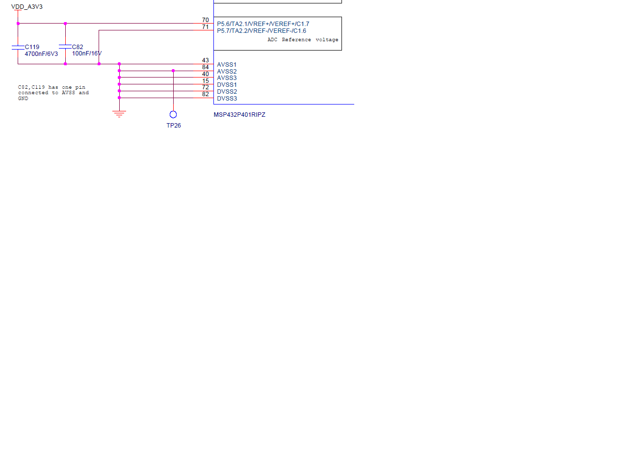
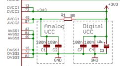
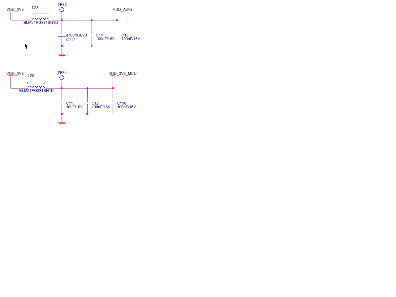
We are developing a custom board with MSP432 at the heart of it. We are seeing massive differences on ADC measured and calculated values. Need urgent help and tips to try. Here is a table showing ADC errors on custom board and EVK launchpad.
| ADC hex count on channel 0 | Decimal Equivalent | 2^14 (14-bit ADC) | Ref Volt | ADC calculated volt | Measured Voltage at pin | Diff measured - ADC o/p | % Error | |||||
| Custom board 1 | 7D0 | 2000 | 16384 | 2.5 | 0.305175781 | 0.318 | 0.012824219 | 4.03% | ||||
| A42 | 2626 | 16384 | 2.5 | 0.400695801 | 0.433 | 0.032304199 | 7.46% | |||||
| 0d8e | 3470 | 16384 | 2.5 | 0.52947998 | 0.582 | 0.05252002 | 9.02% | |||||
| fdc | 4060 | 16384 | 2.5 | 0.619506836 | 0.697 | 0.077493164 | 11.12% | |||||
| 1306 | 4870 | 16384 | 2.5 | 0.743103027 | 0.838 | 0.094896973 | 11.32% | |||||
| 155e | 5470 | 16384 | 2.5 | 0.834655762 | 0.952 | 0.117344238 | 12.33% | |||||
| 189f | 6303 | 16384 | 2.5 | 0.961761475 | 1.106 | 0.144238525 | 13.04% | |||||
| 1Ac2 | 6850 | 16384 | 2.5 | 1.045227051 | 1.2 | 0.154772949 | 12.90% | |||||
| 1E8c | 7820 | 16384 | 2.5 | 1.193237305 | 1.388 | 0.194762695 | 14.03% | |||||
| 231E | 8990 | 16384 | 2.5 | 1.371765137 | 1.68 | 0.308234863 | 18.35% | |||||
| 263C | 9788 | 16384 | 2.5 | 1.493530273 | 1.752 | 0.258469727 | 14.75% | |||||
| 2f3c | 12092 | 16384 | 2.5 | 1.845092773 | 2.194 | 0.348907227 | 15.90% | |||||
| 2c3c | 11324 | 16384 | 2.5 | 1.727905273 | 2.04 | 0.312094727 | 15.30% | |||||
| 333c | 13116 | 16384 | 2.5 | 2.001342773 | 2.387 | 0.385657227 | 16.16% | |||||
| 37dc | 14300 | 16384 | 2.5 | 2.182006836 | 2.616 | 0.433993164 | 16.59% | |||||
| 3bc6 | 15302 | 16384 | 2.5 | 2.334899902 | 2.8 | 0.465100098 | 16.61% | |||||
| 3ec5 | 16069 | 16384 | 2.5 | 2.451934814 | 2.95 | 0.498065186 | 16.88% | |||||
| 3fff | 16383 | 16384 | 2.5 | 2.499847412 | 3.17 | 0.670152588 | 21.14% | |||||
| 3fff | 16383 | 16384 | 2.5 | 2.499847412 | 3.07 | 0.570152588 | 18.57% | |||||
| Custom board 2 | 7ce | 1998 | 16384 | 2.5 | 0.304870605 | 0.33 | 0.025129395 | 7.61% | ||||
| 08f9 | 2297 | 16384 | 2.5 | 0.350494385 | 0.39 | 0.039505615 | 10.13% | |||||
| c0a | 3082 | 16384 | 2.5 | 0.470275879 | 0.532 | 0.061724121 | 11.60% | |||||
| e0a | 3594 | 16384 | 2.5 | 0.548400879 | 0.628 | 0.079599121 | 12.68% | |||||
| 113c | 4412 | 16384 | 2.5 | 0.673217773 | 0.773 | 0.099782227 | 12.91% | |||||
| 13ce | 5070 | 16384 | 2.5 | 0.773620605 | 0.893 | 0.119379395 | 13.37% | |||||
| 166a | 5738 | 16384 | 2.5 | 0.875549316 | 1.016 | 0.140450684 | 13.82% | |||||
| 183c | 6204 | 16384 | 2.5 | 0.946655273 | 1.101 | 0.154344727 | 14.02% | |||||
| 1a92 | 6802 | 16384 | 2.5 | 1.037902832 | 1.212 | 0.174097168 | 14.36% | |||||
| 1ef6 | 7926 | 16384 | 2.5 | 1.209411621 | 1.421 | 0.211588379 | 14.89% | |||||
| 204e | 8270 | 16384 | 2.5 | 1.261901855 | 1.486 | 0.224098145 | 15.08% | |||||
| 24c0 | 9408 | 16384 | 2.5 | 1.435546875 | 1.695 | 0.259453125 | 15.31% | |||||
| 29BC | 10684 | 16384 | 2.5 | 1.630249023 | 1.934 | 0.303750977 | 15.71% | |||||
| 2c1e | 11294 | 16384 | 2.5 | 1.723327637 | 2.049 | 0.325672363 | 15.89% | |||||
| 307e | 12414 | 16384 | 2.5 | 1.894226074 | 2.266 | 0.371773926 | 16.41% | |||||
| 3a8e | 14990 | 16384 | 2.5 | 2.28729248 | 2.737 | 0.44970752 | 16.43% | |||||
| 3c7c | 15484 | 16384 | 2.5 | 2.362670898 | 2.834 | 0.471329102 | 16.63% | |||||
| 3d08 | 15624 | 16384 | 2.5 | 2.384033203 | 2.976 | 0.591966797 | 19.89% | |||||
| EVK1628 | c5a | 3162 | 16384 | 2.5 | 0.48248291 | 0.473 | -0.00948291 | -2.00% | ||||
| 1353 | 4947 | 16384 | 2.5 | 0.754852295 | 0.759 | 0.004147705 | 0.55% | |||||
| 1935 | 6453 | 16384 | 2.5 | 0.984649658 | 1.002 | 0.017350342 | 1.73% | |||||
| 1f2e | 7982 | 16384 | 2.5 | 1.217956543 | 1.246 | 0.028043457 | 2.25% | |||||
| 232b | 9003 | 16384 | 2.5 | 1.373748779 | 1.409 | 0.035251221 | 2.50% | |||||
| 281e | 10270 | 16384 | 2.5 | 1.567077637 | 1.606 | 0.038922363 | 2.42% | |||||
| 2c8e | 11406 | 16384 | 2.5 | 1.74041748 | 1.793 | 0.05258252 | 2.93% | |||||
| 2eea | 12010 | 16384 | 2.5 | 1.832580566 | 1.89 | 0.057419434 | 3.04% | |||||
| 3113 | 12563 | 16384 | 2.5 | 1.91696167 | 1.98 | 0.06303833 | 3.18% | |||||
| 3537 | 13623 | 16384 | 2.5 | 2.078704834 | 2.191 | 0.112295166 | 5.13% | |||||
| 39a9 | 14761 | 16384 | 2.5 | 2.252349854 | 2.381 | 0.128650146 | 5.40% | |||||
| 3f3e | 16190 | 16384 | 2.5 | 2.470397949 | 2.596 | 0.125602051 | 4.84% | |||||
| 3fff | 16383 | 16384 | 2.5 | 2.499847412 | 2.786 | 0.286152588 | 10.27% | |||||
**Attention** This is a public forum